A power grid power failure detection circuit

A power-down detection and power grid voltage technology, applied in the direction of measuring electricity, measuring devices, continuity testing, etc., can solve the problems of complex control, long power-down detection time of the power grid power-down detection circuit, etc., and achieve fewer circuit components and better response Fast speed, effect of eliminating influence

Active Publication Date: 2020-09-25
XJ POWER CO LTD +2
View PDF16 Cites 0 Cited by
  • Summary
  • Abstract
  • Description
  • Claims
  • Application Information

AI Technical Summary

Problems solved by technology

[0006] The purpose of the present invention is to provide a grid power failure detection circuit, which is used to solve the problems of long power failure detection time and complicated control of the grid power failure detection circuit

Method used


Image

  • A power grid power failure detection circuit
  • A power grid power failure detection circuit
  • A power grid power failure detection circuit

Examples


Embodiment Construction

[0020] In order to make the object, technical solution and advantages of the present invention clearer, the present invention will be further described in detail below in conjunction with the accompanying drawings and embodiments.

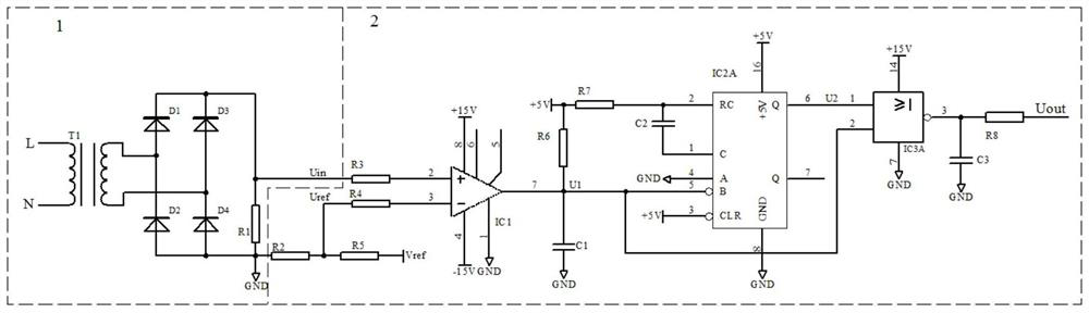
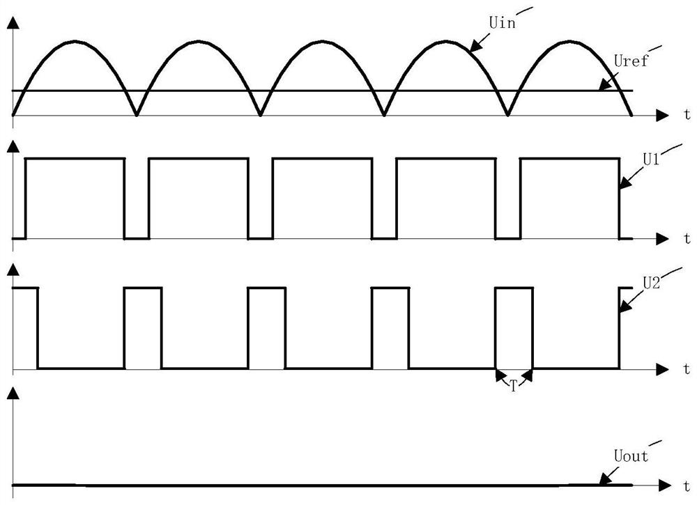
[0021] Depend on figure 2 The schematic diagram of the circuit principle is shown. The grid voltage (L, N) is stepped down by the transformer T1 and rectified by the diodes D1~D4 to become a 100Hz steamed bun wave. After the resistor R1, it finally becomes the output voltage U of the sampling unit in . u in The proportional relationship with the grid voltage is determined by the transformation ratio of the transformer T1 and the conduction voltage drop of the diodes D1-D4.

[0022] According to U in Calculate the reference voltage U ref . When the sampling voltage U in Within a certain period of time (the time is determined by the duration of the monostable trigger IC2 output level) is lower than U ref , it is considered that the grid is p...


PUM


Abstract

The invention relates to the technical field of power grid detection, in particular to a power grid power failure detection circuit. According to key points of the scheme, a voltage detection unit reduces and rectifies a power grid voltage and transmits rectified signals to a judgment unit; the judgment unit compares output signals of the detection unit with the reference voltage, and at the sametime uses a monostable trigger to prevent the judgment error caused by the zero-crossing of a power grid voltage cycle, and outputs the state after comparison in the form of level; a traditional powergrid power failure detection circuit uses an energy storage device or a single chip microcomputer to calculate the waveform, the response time of the circuit is too long, the calculation is complex and the cost of the circuit is high. The power grid power failure detection circuit is realized entirely by discrete devices and does not need programming control over the single chip microcomputer, circuit components are few, the reaction speed is high and the reaction time of the circuit can be adjusted according to the actual situation, and the influence of the zero-crossing of the power grid voltage on the circuit can be eliminated.

Description

technical field [0001] The invention relates to the technical field of grid detection, in particular to a grid power failure detection circuit. Background technique [0002] With the rapid development of social economy, uninterruptible power supplies are more and more widely used in banking, securities, military, medical, aerospace and other fields; and the requirements for fast switching of uninterruptible power supplies are also getting higher and higher. The premise of fast switching is to quickly and accurately detect AC power failure or abnormality. [0003] Since the grid voltage is a sinusoidal 50Hz signal, the voltage waveform will "cross zero" every 10mS. If the power-down detection circuit uses an energy storage device, it can avoid the zero-crossing point of each cycle and prevent the circuit from misjudging, but it will inevitably cause the detection circuit to react too slowly to meet the requirements of fast detection. Therefore, the voltage detection circuit...

Claims


Application Information

Patent Timeline
Patent Type & Authority Patents(China)
IPC IPC(8): G01R31/54G01R31/08
CPCG01R31/086G01R31/50Y04S10/52
Inventor 甘江华罗治军赵启良尹强熊泽成庞浩刘天强于越任晓丹邓长吉华楠王卓琳
Owner XJ POWER CO LTD
Why Eureka
Try Eureka