Device for gas and/or vacuum distribution, suction unit, feeder, sheet processing machine and method for piloting a device for gas and/or vacuum distribution

A distribution device, processing machine technology, applied in the field of plate processing machine, guide the gas and/or vacuum distribution device, suction unit and feeder, can solve the problems of late suction cup advance, fast suction cup mechanical movement, early return position and other issues, to achieve the effect of increasing production speed, limiting cost and weight, and simple structure

Active Publication Date: 2018-12-21
BOBST MEX SA
View PDF10 Cites 1 Cited by
  • Summary
  • Abstract
  • Description
  • Claims
  • Application Information

AI Technical Summary

Problems solved by technology

[0006] In all cases, increasing the speed of the machine results in faster mechanical movement of the suction cups
However, the current problem is that when the system is set to operate at very low and very high speeds, it can cause the suction cups to advance too late or return to position too early

Method used


Image

  • Device for gas and/or vacuum distribution, suction unit, feeder, sheet processing machine and method for piloting a device for gas and/or vacuum distribution
  • Device for gas and/or vacuum distribution, suction unit, feeder, sheet processing machine and method for piloting a device for gas and/or vacuum distribution
  • Device for gas and/or vacuum distribution, suction unit, feeder, sheet processing machine and method for piloting a device for gas and/or vacuum distribution

Examples


Embodiment Construction

[0054] For the sake of clarity, the same elements are denoted by the same reference numerals. At the same time, only elements essential for understanding the invention are shown, which are not shown to scale in a schematic manner.

[0055] portrait, vertical and landscape orientations in Figure 4 is represented by an orthogonal space system (L, V, T).

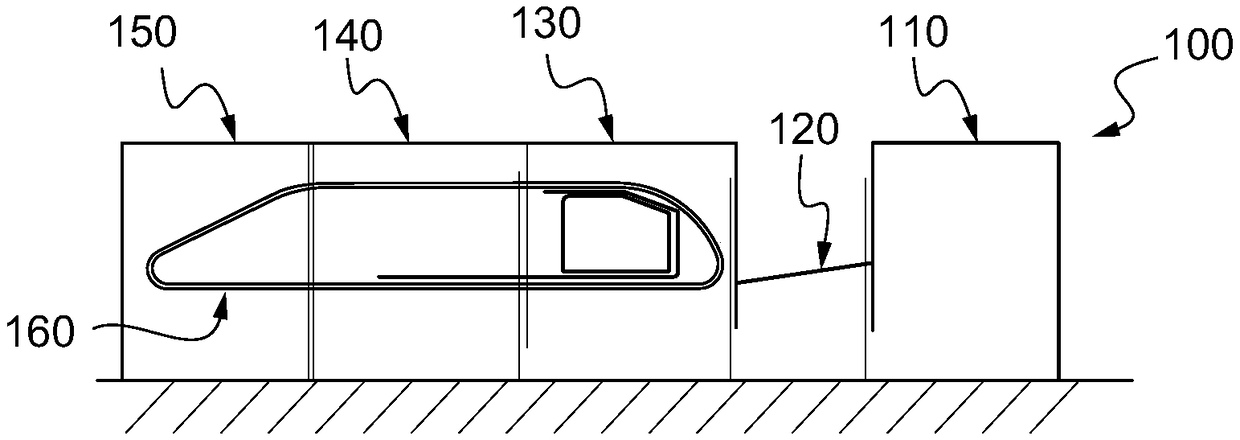
[0056] figure 1 A sheet material processing machine 100 is shown, such as a printing press, die cutter or foil stamping machine.

[0057] The board processing machine 100 allows converting board elements into packaging, for example cardboard packaging. The stamping machine 100, typically comprising a plurality of workstations 110, 120, 130, 140, 150, are arranged side by side to form a monolithic assembly capable of processing a series of flat elements. Therefore, it is necessary to provide an infeed 110 to supply the sheets individually to the machine 100, an infeed table 120 for placing the sheets in layers before precis...


PUM


Abstract

The invention relates to a device for gas and/or vacuum distribution (1) for a sheet processing machine (100). The device for gas and/or vacuum distribution (1) comprises: at least one controllable pilot valve (4; 40), a fixed body (5) comprising: at least one main gas inlet (7) intended to be connected to a gas or vacuum source, at least one main gas outlet (8) intended to be connected to at least one suction cup and/or to at least one nozzle, at least a first and a second control gas openings (10, 11), at least one control gas opening (10, 11) being connected to the controllable pilot valve(4; 40), at least one housing (9) comprising a first chamber (9a) communicating with said main gas inlet (7) and outlet (8) and a second chamber (9b) communicating with the first and second control gas openings (10, 11), at least one mobile piston (6) axially movable in the housing (9) by the action of a control gas or vacuum supplied in the second chamber (9b) through the at least one control gasopening (10, 11) connected to the controllable pilot valve (4; 40), the mobile piston (6) being movable between : a closed position in which the mobile piston (6) blocks a gas path (16) between saidmain gas inlet (7) and outlet (8) in the first chamber (9a), and -an open position in which the mobile piston (6) releases the gas path (16), first and second chambers (9a, 9b) being isolated from each other by cooperation of shapes between the mobile piston (6) and the housing (9) without frictional seal between the mobile piston (6) and the housing (9). The invention also relates to a suction unit and a feeder comprising such a device for gas and/or vacuum distribution. The invention further relates to a sheet processing machine comprising such feeder or such a device for gas and/or vacuum distribution.

Description

technical field [0001] The invention relates to a gas and / or vacuum distribution device for a board processing machine. The invention also relates to a suction unit and a feeder comprising such a gas and / or vacuum distribution device. The invention also relates to a board processing machine comprising the feeder or the gas and / or vacuum distribution device, and a method of guiding the gas and / or vacuum distribution device. Background technique [0002] Board processing machines allow converting boards (e.g. cardboard) into packaging. This operation involves applying decorative or informational printing to the paperboard and cutting it to form the packaging. For this, cardboard is cut into short boards. The boards are stackable and easy to handle, and can be fed into the board processing machine one by one. Sheet processing machines typically consist of a pair of tools, such as cutting or printing rolls or platens, operating at extremely high speeds, with sheets being fed...

Claims


Application Information

Patent Timeline
Patent Type & Authority Applications(China)
IPC IPC(8): F16K31/124B65H3/08F16K27/00
CPCB65H3/0816F16K31/124F16K27/003B65H2406/411B65H3/0891B65H3/08B65H2701/1764
Inventor N·德利厄特拉茨Y·德莱伊
Owner BOBST MEX SA
Why Eureka
Try Eureka