Wastewater treatment system and wastewater treatment method
A wastewater treatment system and biological treatment technology, which is applied in the direction of reflux water treatment, water treatment parameter control, water/sewage multi-stage treatment, etc., can solve the problems of inability to obtain sludge volume reduction effect, poor water quality, and decreased microbial activity in wastewater treatment and other issues to achieve the best sludge volume reduction effect
- Summary
- Abstract
- Description
- Claims
- Application Information
AI Technical Summary
Problems solved by technology
Method used
Image
Examples
Embodiment approach 1
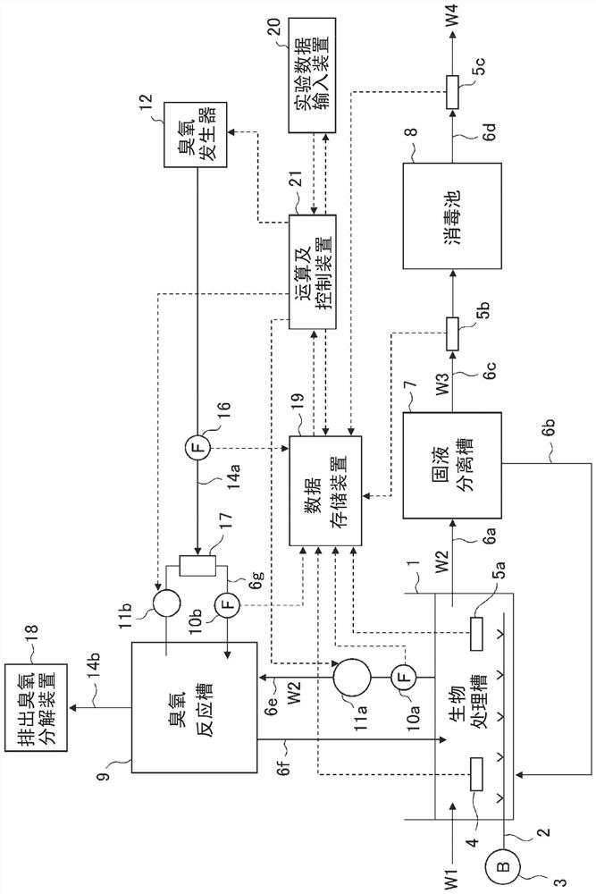
[0029] Hereinafter, a wastewater treatment system and a wastewater treatment method according to Embodiment 1 of the present invention will be described based on the drawings. figure 1 It is a schematic diagram which shows the structure of the wastewater treatment system which concerns on this Embodiment 1. The wastewater treatment system according to Embodiment 1 includes a biological treatment tank 1, an air diffuser 2, a solid-liquid separation tank 7, a disinfection tank 8, an ozone reaction tank 9, an ozone generator 12, and the like. In addition, in figure 1 Among them, W1 is wastewater that is treated water, W2 is sludge-containing treated water, W3 is treated water, and W4 is discharge water.
[0030] In addition, the wastewater treatment method according to the first embodiment mainly includes a biological treatment step, a solid-liquid separation step, and a reforming step. In the biological treatment step, the organic wastewater W1 is biologically treated under ae...
Embodiment approach 2
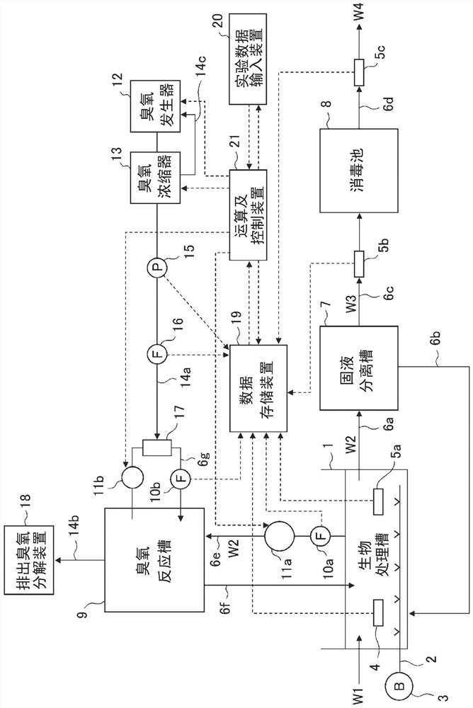
[0076] image 3 It is a schematic diagram which shows the structure of the wastewater treatment system which concerns on Embodiment 2 of this invention. In addition, in image 3 in, right and figure 1 The same parts are marked with the same reference numerals. In the wastewater treatment system according to the second embodiment, the ozone concentrator 13 and the ozone gas pressure gauge 15 are included in the piping 14a for ozone injection. The ozone generator 12 and the ozone concentrator 13 are connected by the piping 14c for oxygen return. The configuration other than the above, and the processing and function of each part are the same as those of the above-described first embodiment, so the description is omitted here.
[0077] The ozone concentrator 13 can condense the ozone generated in the ozone generator 12, and can generate|occur|produce high concentration ozone of 400 mg / L or more and a maximum of 2000 mg / L. The ozone concentrator 13 includes an adsorption towe...
Embodiment approach 3
[0085] Figure 5 It is a schematic diagram which shows the structure of the wastewater treatment system which concerns on Embodiment 3 of this invention. In addition, in Figure 5 in, right and figure 1 The same parts are marked with the same reference numerals. The wastewater treatment system according to the third embodiment includes a plurality of ejectors 17 a , 17 b , and 17 c (collectively referred to as ejectors 17 ) having different nozzle diameters, and an ejector liquid line switching valve 22 and an ejector connected to each ejector 17 . The gas line switching valve 23 is installed. The configuration other than the above, and the processing and function of each part are the same as those in the first and second embodiments described above, and therefore the description is omitted here.
[0086] In the third embodiment, the arithmetic and control device 21 is signal-connected to the ejector liquid line switching valve 22 and the ejector gas line switching valve 2...
PUM
 Abstract
Description
Claims
Application Information
 - R&D
- Intellectual Property
- Life Sciences
- Materials
- Tech Scout
- Unparalleled Data Quality
- Higher Quality Content
- 60% Fewer Hallucinations
Browse by: Latest US Patents, China's latest patents, Technical Efficacy Thesaurus, Application Domain, Technology Topic, Popular Technical Reports.
© 2025 PatSnap. All rights reserved.Legal|Privacy policy|Modern Slavery Act Transparency Statement|Sitemap|About US| Contact US: help@patsnap.com


