
A rotorless jet spray fan

A spray fan and rotorless technology, which is applied in spraying devices, liquid spraying devices, etc., can solve the problems of increasing power per unit area and heat flux density, reducing work efficiency, and small physical size, and achieves fast spraying speed, simple structure, and easy replacement. Strong heat effect

Active Publication Date: 2019-12-31
NAT UNIV OF DEFENSE TECH
View PDF5 Cites 0 Cited by
  • Summary
  • Abstract
  • Description
  • Claims
  • Application Information

AI Technical Summary

Problems solved by technology

[0003] In addition, with the rapid development of electronic technology and MEMS technology, the performance, miniaturization and integration of information systems have been continuously improved. While the total power of electronic devices has increased significantly, the physical size has become smaller and smaller, resulting in power per unit area and The sharp increase of heat flux has made its heat dissipation problem a key bottleneck restricting the development of information systems
Any electronic device / system has its operating temperature range. If effective heat dissipation measures are not taken to ensure that it works at a suitable temperature, it will not only greatly reduce the working efficiency, but also cause the equipment to burn out in severe cases.

Method used


Image

  • A rotorless jet spray fan
  • A rotorless jet spray fan
  • A rotorless jet spray fan

Examples


Embodiment Construction

[0028] Embodiments of the present invention will be further described in detail below in conjunction with the accompanying drawings.

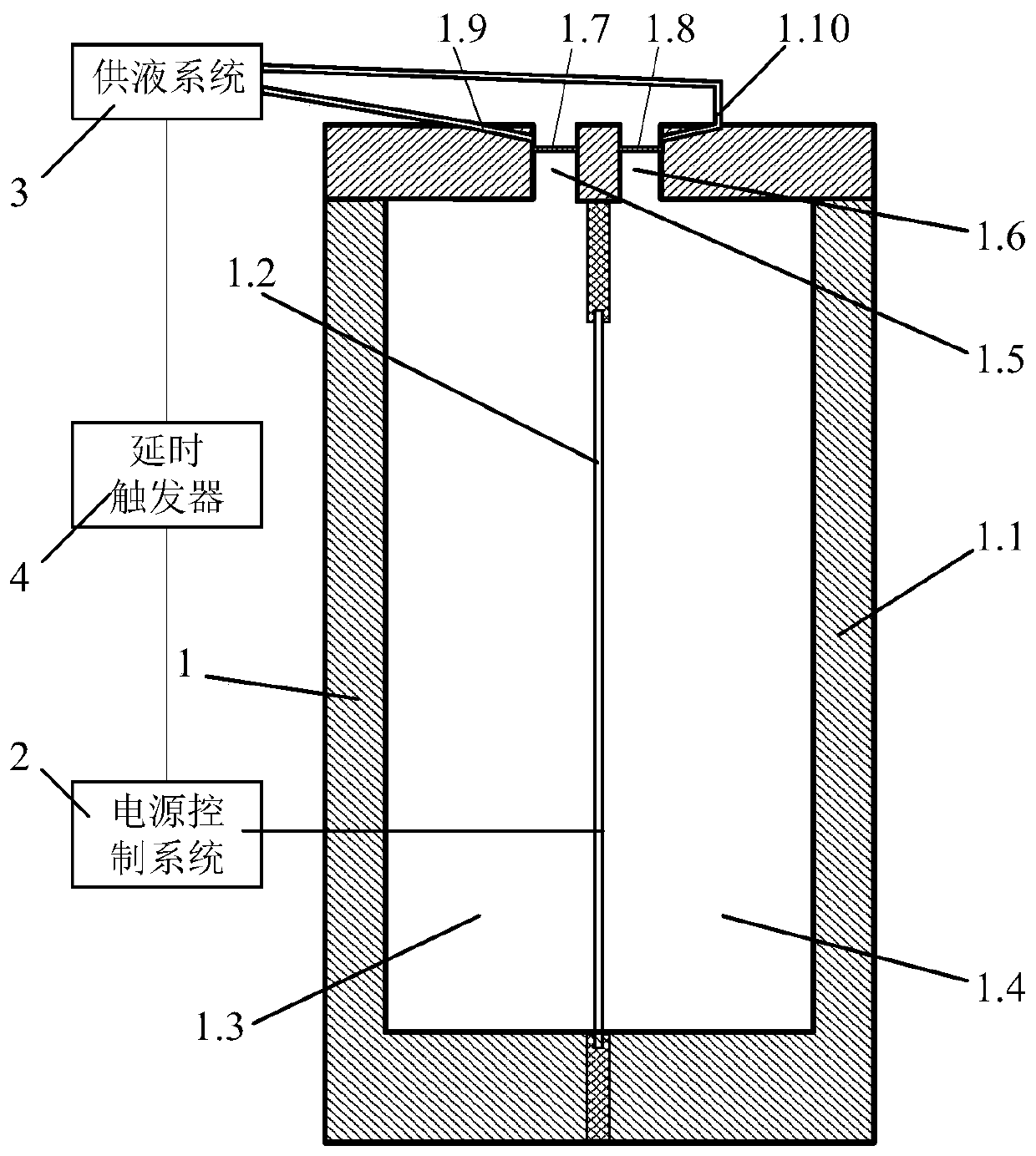
[0029] A rotorless jet spray fan includes a power supply control system 2, a jet exciter 1, a liquid supply system 3 and a delay trigger 4.

[0030] The jet actuator 1 includes a casing 1.1, and the casing 1.1 is provided with a vibrating membrane 1.2. In this embodiment, the vibrating membrane 1.2 is a piezoelectric vibrating membrane, and its vibration is driven by piezoelectricity. The vibrating membrane 1.2 divides the cavity in the housing 1.1 into two independent cavities, respectively the first cavity 1.3 and the second cavity 1.4, and the top wall of the corresponding housing above the first cavity 1.3 is provided with There is a first jet actuator outlet channel 1.5, and a second jet actuator outlet channel 1.6 is provided on the corresponding top wall of the casing above the second cavity 1.4.

[0031] The vibrating membrane 1.2 in t...


PUM


Abstract

A jet spray fan without a rotor comprises a power supply control system, a jet exciter and a liquid supply system. The power supply control system is connected with the jet exciter, and the power supply control system outputs periodic voltage signals to drive a vibration membrane of the jet exciter to vibrate in two independent cavities in the jet exciter in a reciprocated mode, and the two cavities of the jet exciter are alternately compressed and expanded. The liquid supply system is used for supplying liquid needed by mist spraying. The liquid supply system alternately injects liquid to twooutlet channels of the jet exciter. Jet spray mist is alternately formed in the first jet exciter outlet channel corresponding to the first cavity and the second jet exciter outlet channel corresponding to the second cavity. The jet flow spray fan is not provided with the rotor or a bearing, cooling liquid is atomized through the synergistic effect of a sound field, a pressure field and a speed field generated by the vibration membrane. The jet flow spray fan without the rotor has the characteristics of being simple in structure, convenient to control, resistant to high temperatures, high inreliability, good in atomized quality, high in mist spraying speed and the like.

Description

technical field [0001] The invention belongs to the field of fluid machinery and heat and mass transfer, and relates to a rotorless jet spray fan. Background technique [0002] Atomization is the process of spraying a liquid into a gas medium to disperse and break it into small droplets. It is widely used in daily life, industry, agriculture and medical equipment or devices. In daily life, there are atomized humidifiers, atomized aerosols, inkjet printing, etc. In the industrial field, atomization is used for drying, cooling, reaction, spraying, dust removal and other processes, as well as powder metallurgy, printed circuit, 3D printing and other manufacturing In the process of agricultural production, atomization is used for pesticide spraying and agricultural irrigation to improve the utilization rate of drugs and water resources. [0003] In addition, with the rapid development of electronic technology and MEMS technology, the performance, miniaturization and integration...

Claims


Application Information

Patent Timeline
Patent Type & Authority Patents(China)
IPC IPC(8): B05B17/04
CPCB05B17/04
Inventor 邓雄罗振兵夏智勋何伟刘强
Owner NAT UNIV OF DEFENSE TECH
Learn More