Integrated device and method for preparing and forming amorphous alloy composite material

A technology for composite materials and amorphous alloys, which is applied in the field of integrated devices for the preparation and forming of amorphous alloy composite materials, can solve the problems of poor compactness, size restrictions, and the inability to obtain amorphous alloy composite parts in an integrated manner, so as to improve production Efficiency, the effect of breaking through the size limit

Active Publication Date: 2019-01-04
HUAZHONG UNIV OF SCI & TECH
View PDF6 Cites 3 Cited by
  • Summary
  • Abstract
  • Description
  • Claims
  • Application Information

AI Technical Summary

Problems solved by technology

Correspondingly, a kind of amorphous alloy with large size and complex parts is obtained - a metal mesh multilayer sandwich structure amorphous alloy composite material forming device and method, thus solving the problem of the bulk amorphous alloy forming device in the prior art And the technical problems of size limitation, shape limitation, poor compactness and inability to obtain amorphous alloy composite parts in the method

Method used


Image

  • Integrated device and method for preparing and forming amorphous alloy composite material
  • Integrated device and method for preparing and forming amorphous alloy composite material
  • Integrated device and method for preparing and forming amorphous alloy composite material

Examples


Embodiment 1

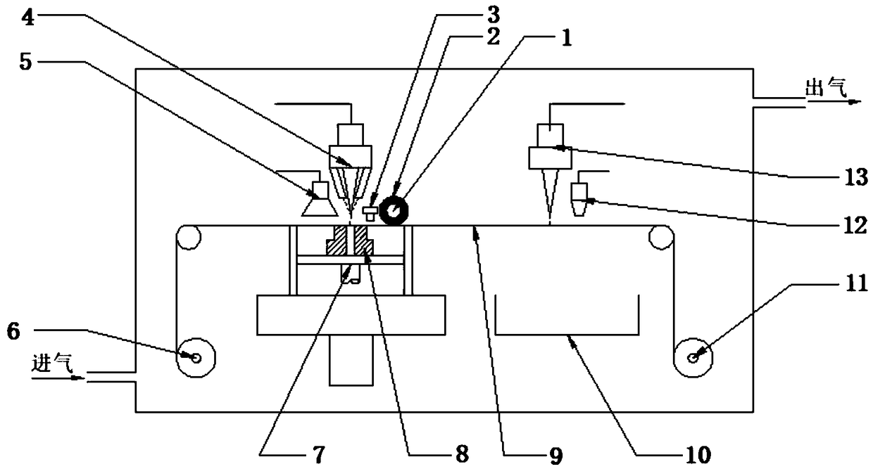
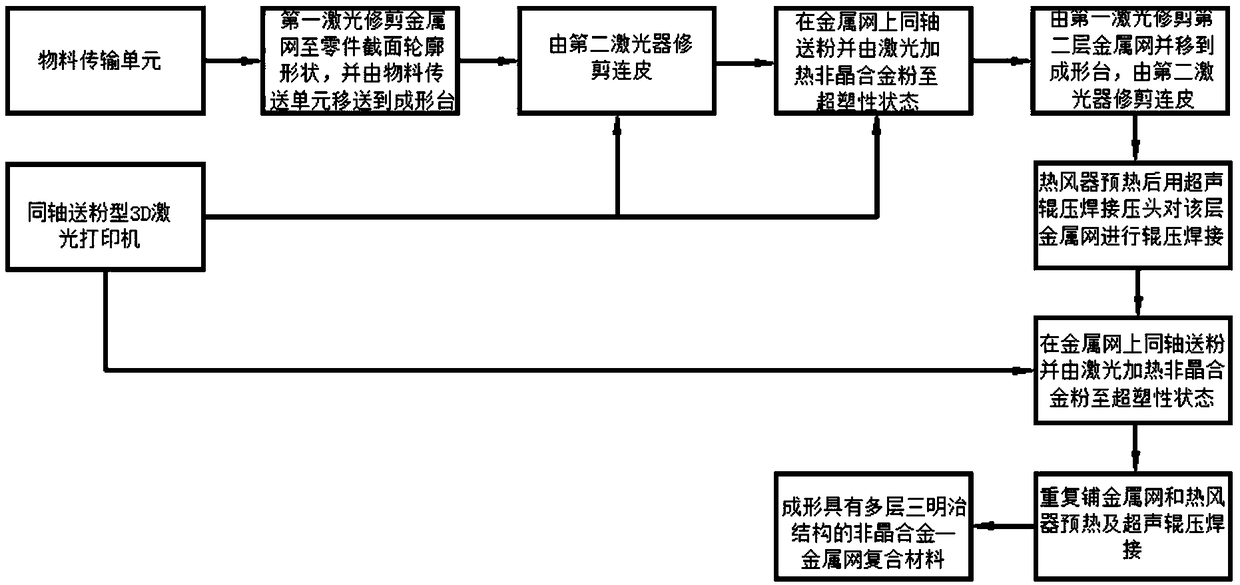
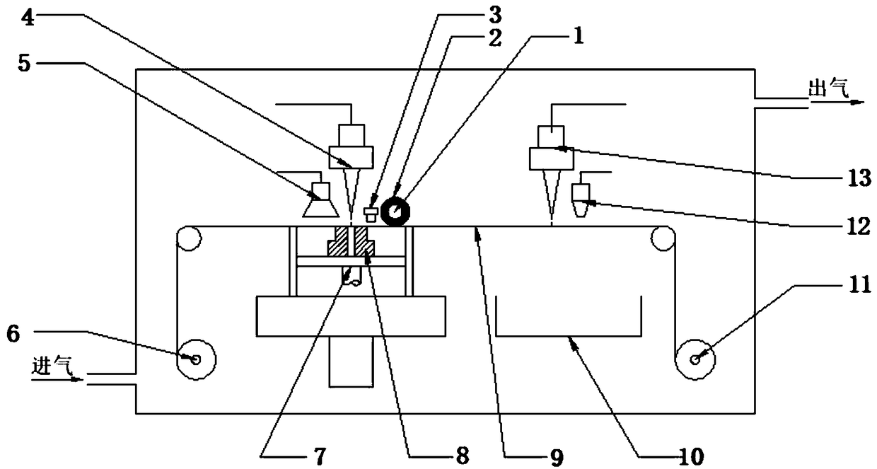
[0085] figure 1 It is a structural diagram of a device for preparing amorphous alloy powder and metal mesh composite material constructed according to a preferred embodiment of the present invention. Such as figure 1 As shown, the device includes a material conveying and trimming part and a composite material forming part, wherein the material conveying and trimming part includes a material conveying unit, that is, an automatic drum feeding device including a feeding drum 11, a feeding belt 9 and a receiving drum 6. In this implementation Among the examples, the feeding device is used to convey the metal mesh, and the first laser 13 placed above the feeding device and the waste collection container that is located under the first laser 13 are the waste collection box 10; the first laser is used for preliminary trimming of the metal The mesh is trimmed to the desired shape and the metal mesh remains intact. The first laser 13 is a coaxial powder feeding laser, which can also ...

Embodiment 2

[0096] image 3 It is a structural diagram of a device for preparing amorphous alloy foil and metal mesh composite material constructed according to a preferred embodiment of the present invention. Such as image 3 As shown, the device includes a material conveying and trimming part and a composite material forming part, wherein the material conveying and trimming part includes a material conveying unit, that is, an automatic drum feeding device including a feeding drum 11, a feeding belt 9 and a receiving drum 6. In this implementation Among the examples, the feeding device is used to transport the metal mesh, the first laser 13 placed above the feeding device and the waste collection container located below the first laser 13, namely the waste collection box 10; the first laser 13 is used for preliminary trimming Metal mesh or amorphous alloy foil to the desired shape and retain the skin after trimming. The composite material forming part is located downstream of the mater...


PUM

PropertyMeasurementUnit
thicknessaaaaaaaaaa
particle sizeaaaaaaaaaa
diameteraaaaaaaaaa

Abstract

The invention belongs to the field of amorphous alloy composite material additive material manufacturing technology and thermoplastic forming, particularly relates to an integrated device and method for preparing and forming amorphous alloy composite material. By reference to a 3D laser printing technology and a roller feeding device principle, by using the advantages of foil build-up welding technology, the forming method of amorphous alloy powder or amorphous alloy foil is targeted to redesign, the integrated device and method for forming the amorphous alloy composite material with large size and complex parts of amorphous alloy with metal net multilayer sandwich structure is correspondingly obtained, and thus the existing technical problems of the limitation of size and shapes, and poorcompact degree in a block amorphous alloy composite material forming device and method are solved.

Description

technical field [0001] The invention belongs to the fields of additive manufacturing technology and thermoplastic forming of amorphous alloy composite materials, and more specifically relates to an integrated device and method for preparing and forming amorphous alloy composite materials. Background technique [0002] Due to its unique amorphous structure, amorphous alloys have significantly better mechanical, physical and chemical properties than traditional crystalline alloys, such as high strength, good wear resistance and corrosion resistance, and in supercooled liquid phase Amorphous alloys also exhibit superplasticity. In many fields such as aerospace, precision instruments, and military chemicals, amorphous alloys have broad application prospects. However, as structural materials, the fatal defect of amorphous alloys is the lack of macroscopic room temperature plastic deformation ability, and the room temperature brittleness of amorphous alloys greatly limits its appl...

Claims


Application Information

Patent Timeline
Patent Type & Authority Applications(China)
IPC IPC(8): B22F3/105B22F3/18B22F3/24C22C1/00C22C45/10
CPCC22C45/10B22F3/18B22F3/24B22F2003/247B22F10/00B22F12/45B22F10/25B22F12/17B22F12/86B22F10/50C22C1/11Y02P10/25
Inventor 龚攀马云飞王新云莫健华李宁邓磊金俊松
Owner HUAZHONG UNIV OF SCI & TECH
Why Eureka
Try Eureka