Casting process of bearing seat

A processing technology and bearing seat technology, which is applied in the field of bearing seat casting processing technology, can solve the problems of high cost of wind power generation, high usage of ceramic tubes and chilled iron, and unreasonable ratio of raw materials, etc., to achieve favorable clamping The effect of slag floating up, reducing the amount of cold iron used, and no riser

Active Publication Date: 2020-10-09
惠尔信机械(泰兴)有限公司
View PDF4 Cites 0 Cited by
  • Summary
  • Abstract
  • Description
  • Claims
  • Application Information

AI Technical Summary

Problems solved by technology

[0002] The use of wind power generation is very environmentally friendly, and the wind energy reserves are huge, so it is increasingly valued by countries all over the world; human beings rarely develop and utilize wind energy. Now the only wind power generator in the world is a three-leaf one-column. During its installation and use, the The wind source requirements of the environment are high. At the same time, this type of wind turbine has many restrictions on the size and huge investment, which also leads to the high cost of wind power generation.
The development trend of wind power generators is that the power is getting bigger and bigger, and the specifications and sizes are getting bigger and bigger accordingly. At present, the casting and pouring system of wind power bearing housing is the traditional low temperature fast pouring system, which uses a large number of ceramic tubes and chilled iron. Complex process, high labor intensity and high cost
Due to the large amount of ceramic tubes and chill irons used, the cleaning of ceramic tubes and chill irons affects the mold clamping efficiency; the original pouring system is a traditional low-temperature fast pouring pouring system, a large number of ceramic tubes are used, the process is complex, labor-intensive and costly
The original pouring system is a traditional low-temperature fast pouring system, which uses a large number of chilled irons, which is complicated in process, labor-intensive and high in cost.
In addition, the raw material ratio of the original casting and pouring process is not reasonable, and the method of low-temperature rapid pouring is required, and chilled iron is used. In this way, the oxide slag formed by the contact between the chilled iron and the molten iron has poor surface properties of the casting, and due to the ceramic tube and The amount of cold iron used is large, and the cleaning of ceramic tubes and cold iron affects the mold clamping efficiency

Method used


Image

  • Casting process of bearing seat
  • Casting process of bearing seat
  • Casting process of bearing seat

Examples


Embodiment 1

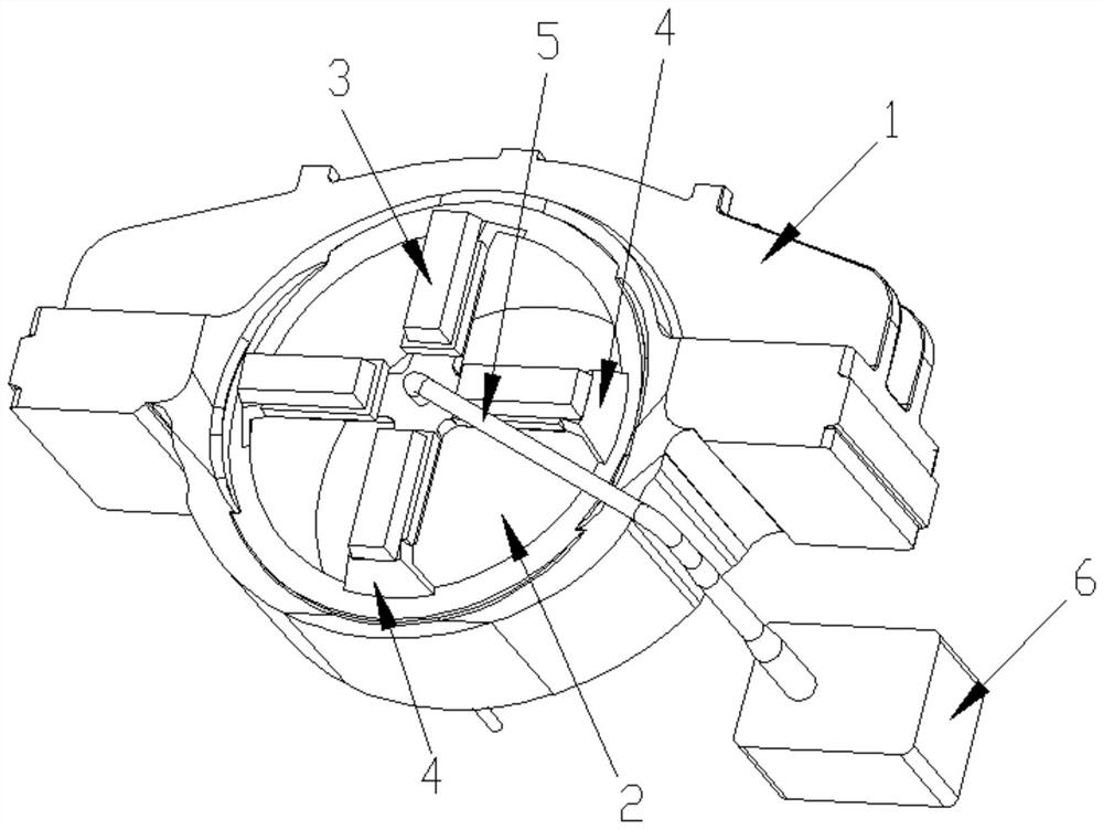
[0026] The present invention is a kind of bearing housing casting processing technology, including the following process steps:

[0027] S1: First heat and melt the smelting charge in an electric furnace until it reaches 1465°C and release it from the furnace; the smelting charge is composed of the following components by weight percentage: 40% pig iron, 49% scrap steel, 10% recycled material, and 1% recarburizer.

[0028] S2: During the process of molten iron coming out of the furnace, metal antimony with a concentration of 50 parts per million is washed into the ladle with the flow, and the molten iron is poured into the spheroidizing ladle after standing and slag removal;

[0029] S3: After the molten iron is injected into the spheroidizing ladle from the spheroidizing ladle mouth, it first enters the first pit of the spheroidizing ladle for refining, and then the molten iron floods the dam of the spheroidizing ladle and then enters the second and third pits of the spheroidi...

Embodiment 2

[0037] The difference from Example 1 is that the smelting charge is composed of the following components by weight percentage: 39% pig iron, 50% scrap steel, 10% returned charge, and 1% recarburizer. In the second pit and the third pit, 1.00% by weight of nodulizer, 0.1% by weight of inoculant and 0.4% by weight of covering agent are added;

[0038] The composition of molten iron before and after nodularization is as follows:

[0039] Raw water: C: 3.75; Si: 1.4; Mn: 0.13; P: 0.04; S: 0.007; Cr: 0.03; Cu: 0.05; Ni: 0.05; Ti: 0.03; Sn: 0.01;

[0040] Final water: C: 3.64; Si: 2.05; Mn: 0.13; P: 0.04; S: 0.01; Mg: 0.028; Cr: 0.03; Cu: 0.05; Ni: 0.05; Ti: 0.03; Sn: 0.01; ~0.006.

Embodiment 3

[0042] The difference from Example 1 is that the smelting charge is composed of the following components by weight percentage: 40% pig iron, 50% scrap steel, 9% returned charge, and 1% recarburizer. Both the second pit and the third pit are added with 1.00% by weight of nodulizer, 0.1% by weight of inoculant and 0.6% by weight of covering agent;

[0043] The composition of molten iron before and after nodularization is as follows:

[0044] Raw water: C: 3.80; Si: 1.5; Mn: 0.18; P: 0.04; S: 0.015; Cr: 0.03; Cu: 0.05; Ni: 0.05; Ti: 0.03; Sn: 0.01;

[0045] Final water: C: 3.66; Si: 2.15; Mn: 0.18; P: 0.04; S: 0.01; Mg: 0.038Cr: 0.03; Cu: 0.05; Ni: 0.05; Ti: 0.03;

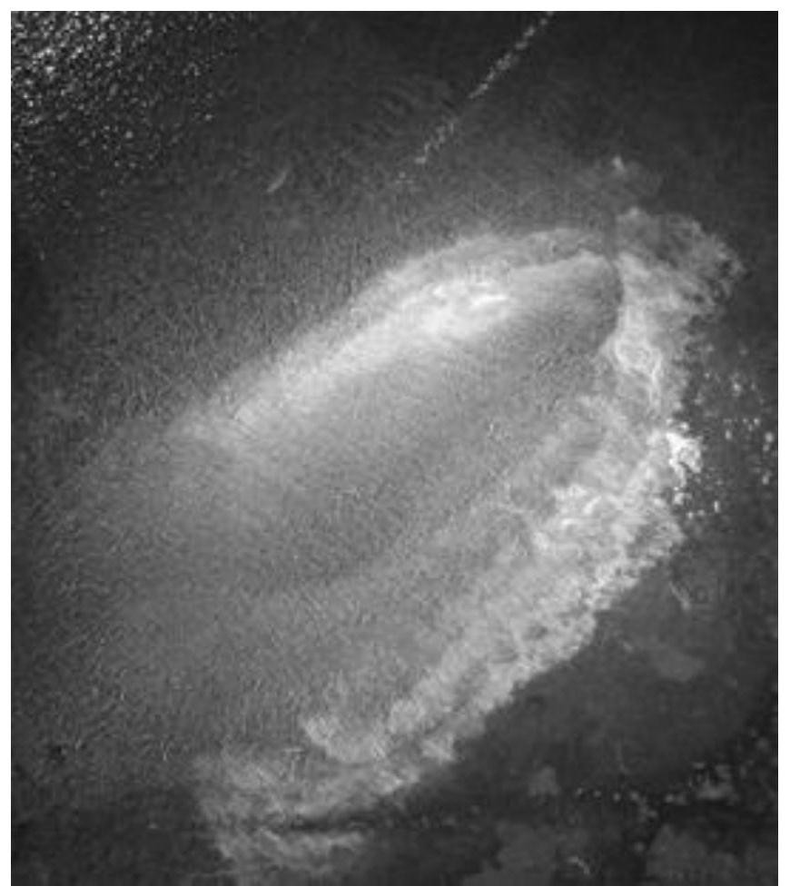
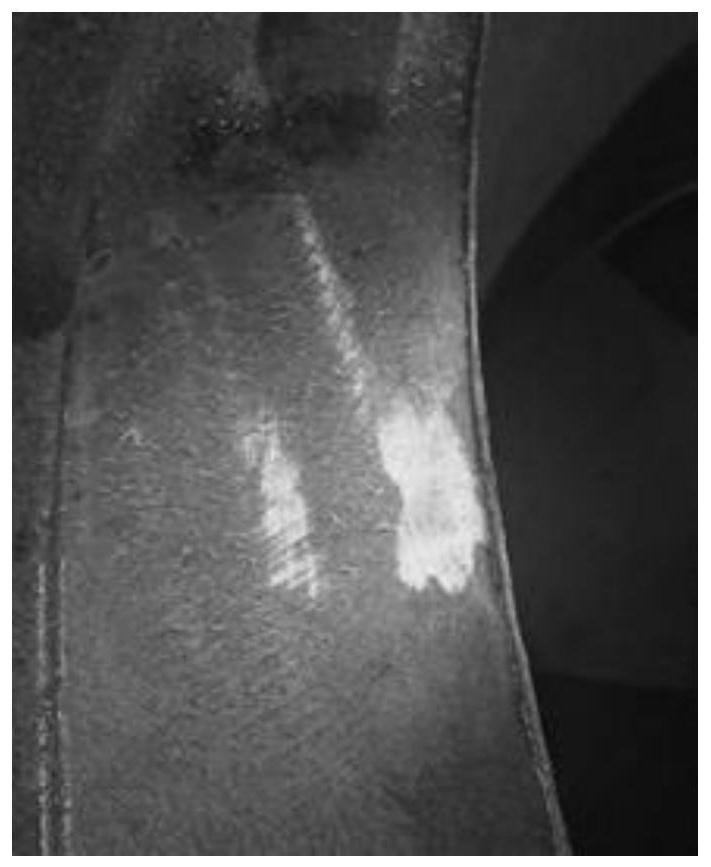
[0046] The surface performance has been greatly improved. After the surface magnetic particle inspection, it was found that the thickest part of the surface defect (scum layer thickness) of the new process is about 2mm (the thickness of the original surface defect is about 5-10mm, such as figure 2 ),Such as image...


PUM

PropertyMeasurementUnit
thicknessaaaaaaaaaa
thicknessaaaaaaaaaa

Abstract

The invention discloses a bearing block casting process. The bearing block casting process. The bearing block casting process includes: heating to melt smelting furnace charge in an electric furnace,and discharging when the temperature reaches 145 DEG C, wherein the smelting furnace charge comprises, by weight percentage, 30-45% of pig iron, 35-55% of waste steel, 5-20% of foundry returns and 1%of carburant; during molten iron discharge, washing antimony into a casting ladle along with flow, and injecting into balling ladle; after the molten iron is injected into the balling ladle from a ladle mouth, refining the molten iron in the first pit of the balling ladle, and subjecting the molten iron to balling inoculation in the second pit and the third pit of the balling ladle after the molten iron overflows the dam of the balling ladle, wherein the balling agent is Elkem5813, the balling agent is covered with an Elkem inoculant, the inoculant is covered with a covering agent, and the balling temperature is 1440-1460 DEG C; when the temperature of the molten iron reaches 1350-1370 DEG C, using a high-temperature slow pouring process coordinated with a fash pouring method to pour a wind power cast in a resin sand mould. The bearing block casting process has the advantages that pouring temperature is increased, pouring speed is lowered, slagging is benefited, and cast surface performance is increased.

Description

technical field [0001] The invention relates to a casting process of a bearing seat. Background technique [0002] The use of wind power generation is very environmentally friendly, and the wind energy reserves are huge, so it is increasingly valued by countries all over the world; human beings rarely develop and utilize wind energy. Now the only wind power generator in the world is a three-leaf one-column. During its installation and use, the The wind source requirements of the environment are high. At the same time, this type of wind turbine has many restrictions on the size and huge investment, which also leads to the high cost of wind power generation. The development trend of wind power generators is that the power is getting bigger and bigger, and the specifications and sizes are getting bigger and bigger accordingly. At present, the casting and pouring system of wind power bearing housing is the traditional low temperature fast pouring system, which uses a large numbe...

Claims


Application Information

Patent Timeline
Patent Type & Authority Patents(China)
IPC IPC(8): C22C37/10C22C37/08C22C37/04C22C33/08B22C9/02B22C9/08B22C9/22
CPCB22C9/02B22C9/08B22C9/22C22C33/08C22C37/04C22C37/08C22C37/10
Inventor 徐惠民高嘉伟何军
Owner 惠尔信机械(泰兴)有限公司
Why Eureka
Try Eureka