Thermal non-contact voltage and non-contact current devices

A non-contact, measurement equipment technology, applied in non-contact circuit testing, voltage/current isolation, phase angle between voltage and current, etc., can solve the problem that infrared imaging cannot quantify energy loss, etc.

Pending Publication Date: 2019-01-04
弗兰克公司
View PDF14 Cites 5 Cited by
  • Summary
  • Abstract
  • Description
  • Claims
  • Application Information

AI Technical Summary

Problems solved by technology

Unfortunately, while being able to spot the location and source of high resistance problems is invaluable to electricians, engineers, and other maintenance professionals, infrared imaging alone often cannot quantify the amount of energy loss in a practical way

Method used


Image

  • Thermal non-contact voltage and non-contact current devices
  • Thermal non-contact voltage and non-contact current devices
  • Thermal non-contact voltage and non-contact current devices

Examples


Embodiment Construction

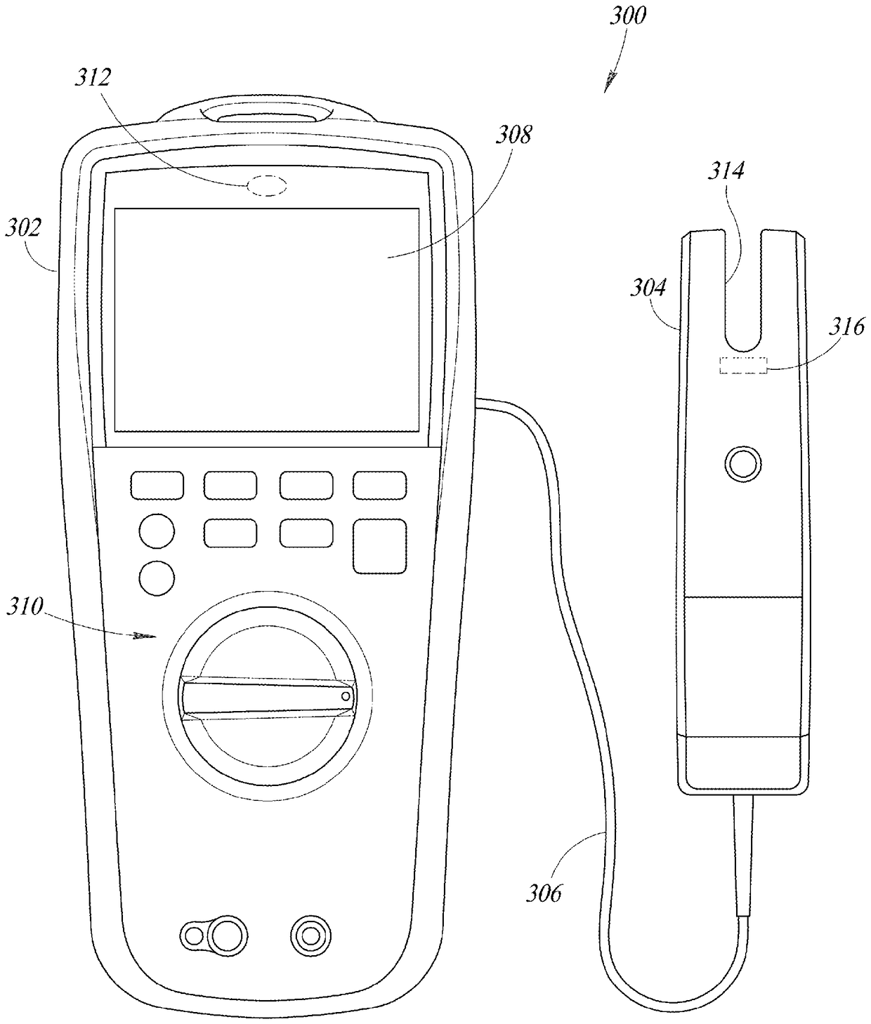
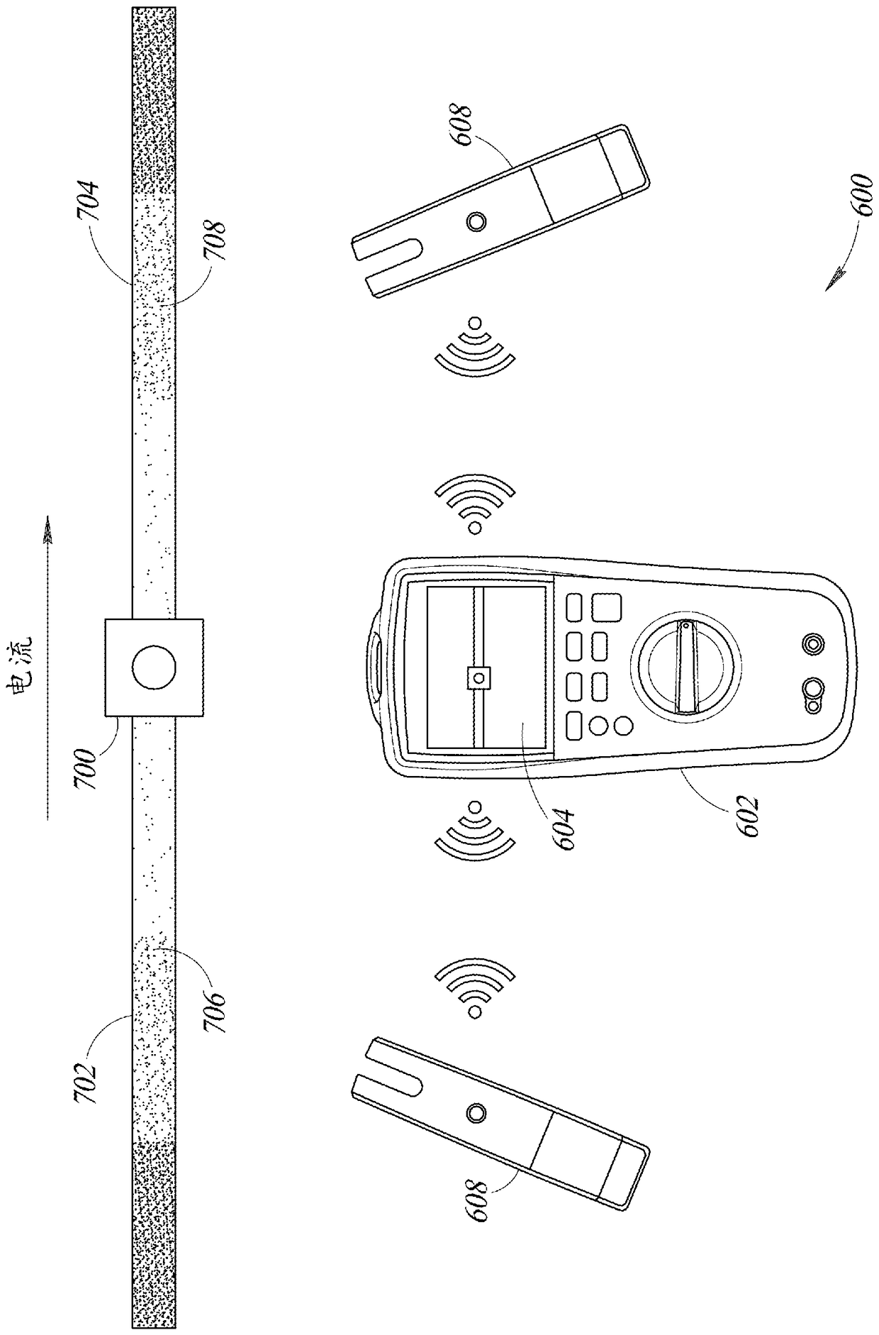
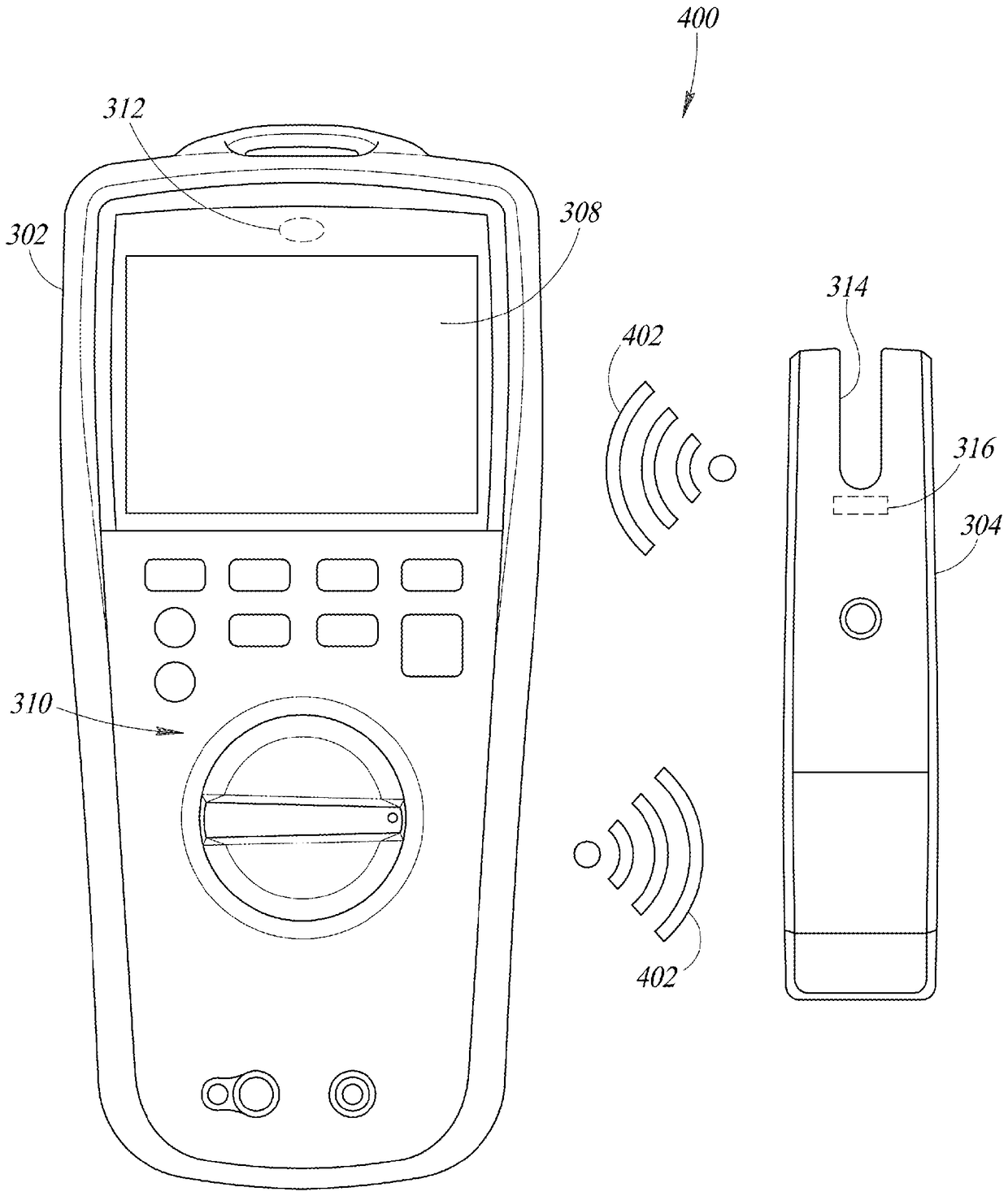
[0023] One or more implementations of the present disclosure provide systems and methods that provide thermal imaging and non-contact voltage or current measurement sensors to detect or measure anomalies in electrical circuits. Such systems and methods may be implemented in a single test device, or in a wired combination, or in wireless communication with multiple test devices and / or accessories, or with one or more additional devices such as mobile phones, tablets, A combination of personal computers (PCs), cloud-based servers, etc. is implemented.

[0024] In at least some implementations, a thermal imaging system or tool of a measurement device including an infrared sensor may first find and image one or more thermal anomalies in an object, such as an electrical circuit. A user or measurement device may then analyze the detected thermal patterns, which may indicate a localized high resistance electrical connection, or high resistance due to incorrect conductor or component ...


PUM


Abstract

The invention is entitled thermal non-contact voltage and non-contact current devices. Systems and methods detect abnormal conditions in electrical circuits by providing thermal imaging combined withnon-contact measurements of current and voltage. Such systems may be implemented in a single test device, or in wired combinations, or in wireless communication implementations with multiple test devices and / or accessories, or in combination with one or more additional devices, such as a mobile phone, tablet, personal computer (PC), cloud-based server, etc. A thermal imaging tool that includes aninfrared sensor may first discover and image one or more thermal anomalies in an object, such as an electrical circuit. One or more non-contact current or voltage sensors may be used to measure current and / or voltage, which allows for determination of the power loss at the measured location. The power loss may be used to determine an estimation of the abnormal resistive power losses in a circuit,as well as the costs associated therewith.

Description

[0001] Background technique. technical field [0002] The present disclosure generally relates to non-contact measurement or detection of various characteristics of electrical circuits. Background technique [0003] High resistance electrical connections can result in power loss in the circuit. Such connections are often referred to as "resistive power loss," "copper loss," or "I 2 R loss". This formula is a transformation of Ohm's law V = IR, which describes the relationship between current (I), voltage (V) and resistance (R). The related formula is P = VI, which states that power (P ) is equal to the current multiplied by the voltage. According to the above formula, the power loss can be obtained by the formula P = I 2 R OK. From this formula, it is known that energy or power loss increases with the square of the current (I) through the conductor and is proportional to the resistance (R) of the conductor. [0004] In the presence of resistive power loss in a circuit, t...

Claims


Application Information

Patent Timeline
Patent Type & Authority Applications(China)
IPC IPC(8): G01R19/00G01R21/06G01R23/02G01R23/16G01R25/00
CPCG01R19/00G01R21/06G01R23/02G01R23/16G01R25/00G01R21/02G01R21/08H02J13/00001H02J13/00002Y04S10/30Y04S10/40Y02E60/00G01R31/308G01R15/24G01R15/181G01R15/202G01R15/205
Inventor L.R.西尔瓦M.D.斯图尔特
Owner 弗兰克公司
Why Eureka
Try Eureka