Mechanical low-frequency vibration drilling device

A low-frequency vibration, mechanical technology, applied in the direction of boring/drilling, drilling/drilling equipment, boring machine/drilling machine parts, etc., can solve the problem of inability to achieve high-speed rotational axial vibration, inability to achieve quick adjustment of amplitude, and limitations Vibration hole making technology and other issues to achieve the effect of improving cooling and lubrication effects, solving the problem of chip breaking and chip removal, and good economic benefits

Pending Publication Date: 2019-01-08
HENAN POLYTECHNIC UNIV
View PDF3 Cites 3 Cited by
  • Summary
  • Abstract
  • Description
  • Claims
  • Application Information

AI Technical Summary

Problems solved by technology

The electromagnetic axial vibration device has a simple structure and a wide range of vibration frequency adjustment, but the power of the electromagnetic exciter is small, and it is only suitable for the processing of tiny holes, especially if it is used on a rotating spindle or tool holder, it still needs to be solved Electrical transmission problems, resulting in complex structure and high cost
The mechanical vibration drilling device has simple structure, good rigidity and long service life. However, at present, the vibration device often adopts an eccentric wheel mechanism, which is inconvenient to adjust the amplitude and requires an additional power source. It cannot be directly installed on the spindle, and it is difficult to achieve Vibration is performed while rotating at high speed, and springs are generally used in these devices to generate elastic recovery force, resulting in poor rigidity of the process system and poor amplitude stability in vibration drilling, which limits the application of vibration drilling technology
At present, scholars have proposed a device that is installed at the end of the spindle and uses the rotation of the spindle as power to realize the axial vibration of the tool, such as the patent "A Vibration Device for Drilling" (application number 03137581.2, publication number CN1476949A, publication date: 2004.2 .25) The invented vibration device can convert the rotary motion input by the main shaft of the drilling machine into the composite motion of the rotary motion and axial vibration of the vibration main shaft, but the main shaft of the device is installed in the middle casing through the radial roller bearing and the linear bearing, There is a long dimensional chain from the machine tool spindle to the device spindle, which limits the rotation accuracy of the spindle to a certain extent. In addition, the device uses a double-sided cylindrical cam, which cannot achieve quick adjustment of the amplitude.
Patent "A single-point incremental forming tool head axial vibration device" (application number CN201410637206.5, publication number 106583538A, publication date: 2017.4.26) invented the single-point incremental forming tool head axial vibration device, through the machine tool The rotation of the main shaft drives the tool head with the ejector rod to generate axial vibration, but this device can only realize the axial vibration of the tool head, and cannot achieve axial vibration while rotating at high speed

Method used


Image

  • Mechanical low-frequency vibration drilling device
  • Mechanical low-frequency vibration drilling device
  • Mechanical low-frequency vibration drilling device

Examples


Embodiment

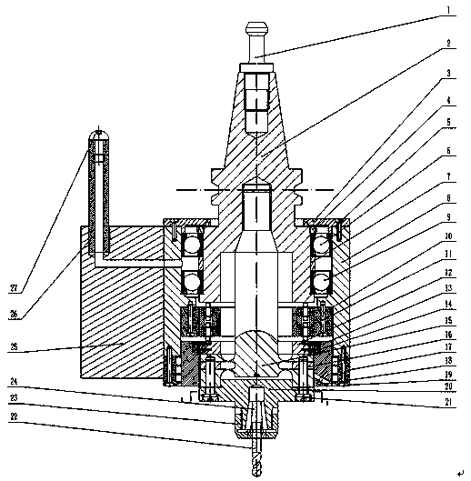
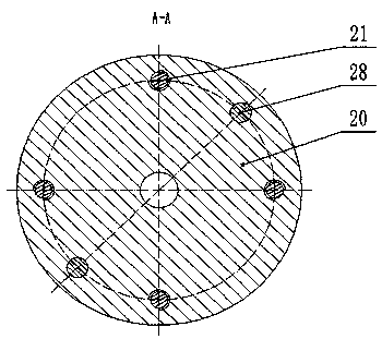
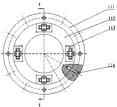
[0022] Example: see Figure 1-Figure 4 , in the figure, 1-pull stud, 2-end cam with tapered shank, 3-sealing cover ring, 4-compression nut, 5-screw, 6-angular contact ball bearing, 7-spacer, 8-device shell, 9-angular contact ball bearing, 10-screw, 11-fixed disc, 12-driven cam, 13-female key, 14-screw, 15-annular flexible hinge, 16-supporting half disc, 17-sealing ring , 18-adjusting nut, 19-screw, 20-vibration output rod, 21-screw, 22-drill, 23-nut, 24-spring collet, 25-shell fixing handle, 26-shell fixing rod, 27-cap, 28-location pin, 111-fixed disc inner ring, 112-fixed disc inner ring, 113-slider, 1131-slider body, 1132-support roller bearing, 1133-snap ring, 1134-support shaft, 114-screw.

[0023] A mechanical low-frequency vibration drilling device of the present invention includes six components such as a device housing 8, a tapered shank end cam 2, a driven end cam 12, a fixed disc 11, an annular flexible hinge 15 and a vibration output rod 20.

[0024] The device ca...


PUM

PropertyMeasurementUnit
Surface hardnessaaaaaaaaaa

Abstract

The invention discloses a mechanical low-frequency vibration drilling device. The outer surface of the lower end of an end face cam with a taper shank is rotationally connected with the upper portionof an inner cavity of a device shell. An annular flexible hinge is arranged in the inner cavity of the device shell. A vibration output rod is arranged at the lower end of the annular flexible hinge,and a driven end face cam is arranged on the upper portion of the annular flexible hinge. The lower end face of the end face cam with the taper shank and the upper end face of the driven end face camare both sine-ruled surfaces. A fixed disc is arranged in the middle of the inner cavity of the device shell, and penetrating holes are evenly distributed in the fixed disc along the circumference. Each penetrating hole is internally provided with a sliding block. Idler wheels are arranged at the two ends of each sliding block correspondingly, wherein the two idler wheels are in rolling contact with the lower end face of the end face cam with the taper shank and the upper end face of the driven end face cam. According to the mechanical low-frequency vibration drilling device, through rotationof a main shaft, low-frequency axial vibration is generated while the vibration output rod rotates at the high speed, and precise and efficient drilling of materials such as titanium alloys and composite materials which are difficult to machine is achieved.

Description

Technical field: [0001] The invention relates to a drilling device in mechanical processing, in particular to a mechanical low-frequency vibration drilling device. Background technique: [0002] Hole machining is one of the important processes in machining. With the development of science and technology, the demand for precision drilling on some difficult-to-machine materials such as titanium alloys, stainless steel, composite materials, etc. is getting higher and higher, especially when drilling small deep holes on these materials, due to the diameter of the drill Small size, poor rigidity, low strength, the drill bit is easy to break, due to the high toughness of the material, it is not easy to break and remove chips, and the high temperature of deep hole drilling makes the drill bit wear seriously and the hole processing quality is difficult to guarantee. With the continuous improvement of the requirements for hole processing quality and efficiency, the traditional drill...

Claims


Application Information

Patent Timeline
IPC IPC(8): B23B39/00B23B47/00
CPCB23B39/00B23B47/00Y02P70/10
Inventor 焦锋李远霄王东王晓博封志彬王晓亮童景琳赵波
Owner HENAN POLYTECHNIC UNIV
Why Eureka
Try Eureka