A Fast Response Charge Pump Circuit for Phase Locked Loop

A fast-response, charge-pump technology, applied in the direction of electrical components, automatic power control, and conversion equipment without intermediate conversion to AC, can solve the problem of affecting the performance of the phase-locked loop loop, the charging/discharging current matching range is small, and the charging /Discharge current matching accuracy is low, to overcome the channel length modulation effect, improve the matching range, and avoid the effect of inherent mismatch

Active Publication Date: 2022-03-22
CHONGQING UNIV OF POSTS & TELECOMM
View PDF7 Cites 0 Cited by
  • Summary
  • Abstract
  • Description
  • Claims
  • Application Information

AI Technical Summary

Problems solved by technology

[0004] However, traditional charge pumps have problems such as low matching accuracy of charging / discharging current and small matching range of charging / discharging current, which directly affect the loop performance of the phase-locked loop.

Method used


Image

  • A Fast Response Charge Pump Circuit for Phase Locked Loop
  • A Fast Response Charge Pump Circuit for Phase Locked Loop
  • A Fast Response Charge Pump Circuit for Phase Locked Loop

Examples


Embodiment

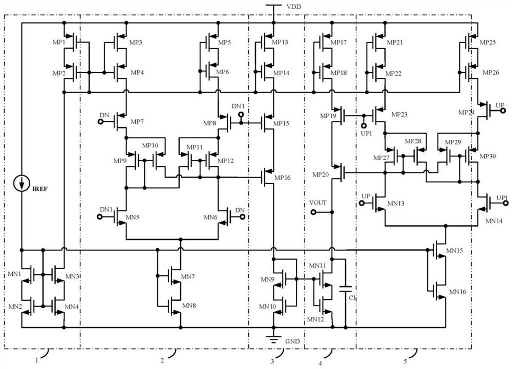
[0030] A fast-response charge-pump circuit for phase-locked loops, such as figure 2 As shown, it includes a self-biased cascode bias circuit 1, a DN differential digital-to-analog conversion circuit 2, a replica circuit 3, a charging and discharging circuit 4, and a UP differential digital-to-analog conversion circuit 5;

[0031] Wherein, the signal output terminals of the self-biased cascode bias circuit 1 are connected to the DN differential digital-to-analog conversion circuit 2, the replica circuit 3, the charging and discharging circuit 4, and the UP differential digital-to-analog conversion circuit respectively. The signal input terminal of the conversion circuit 5, the signal output terminal of the DN differential digital-to-analog conversion circuit 2 is connected to the signal input terminal of the replication circuit 3, the signal output of the replication circuit 3 and the UP differential digital-to-analog conversion circuit 5 Terminate the signal input end of the ...


PUM


Abstract

The present invention claims a fast-response charge pump circuit for a phase-locked loop, including a self-biased cascode bias circuit, a DN differential digital-to-analog conversion circuit, a replica circuit, a charge-discharge circuit, and a UP differential digital-to-analog conversion circuit . The self-biased cascode bias circuit is used to provide current bias for the core circuit of the charge pump, which effectively overcomes the channel length modulation effect of a single MOS tube and improves the matching accuracy of the charging current and discharging current of the charge pump. Compared with the cascode bias circuit, the output voltage swing of the charge pump circuit is improved, and the power supply voltage is reduced at the same time; the upper and lower current sources are used to provide the charge and discharge current, which suppresses the change of the charge / discharge current with the output voltage and improves the charge. The charging / discharging current matching range of the pump; the same type of switching tube is used as the switch of the charge pump, which effectively avoids the inherent mismatch between different switching tubes; the positive feedback mechanism is adopted to improve the response speed of the switching tube.

Description

technical field [0001] The invention belongs to the field of integrated circuit design, and in particular relates to a fast-response charge pump circuit for a phase-locked loop. Background technique [0002] The charge pump phase-locked loop has the advantages of wide capture range, short capture time, large linear range, high speed and low power consumption, and has been widely used in modern communication and radio frequency fields. The charge pump phase-locked loop is mainly composed of five parts: phase frequency detector (PFD), charge pump (CP), loop filter (LPF), voltage controlled oscillator (VCO) and frequency divider (Divider). Among them, the charge pump circuit is the main circuit module in the charge pump phase-locked loop. Its main function is to convert the digital control signal (including charging signal and discharging signal) output by the phase frequency detector (PFD) into an analog signal, and then control The output frequency of the voltage-controlled ...

Claims


Application Information

Patent Timeline
Patent Type & Authority Patents(China)
IPC IPC(8): H03M1/66H03L7/08H02M3/07
CPCH02M3/07H03L7/08H03M1/66
Inventor 周前能王程程李红娟周思敏陈思良
Owner CHONGQING UNIV OF POSTS & TELECOMM
Why Eureka
Try Eureka