
A kind of zone oxidation ozone distributor and its layout and application

A distributor and ozone technology, applied in chemical instruments and methods, separation methods, dispersed particle separation, etc., can solve the problems of large ozone consumption, reduction of oxidation, ozone escape, etc., and achieve strong operability, rapid response, The effect of reducing the cost-benefit ratio

Active Publication Date: 2020-09-15
INST OF PROCESS ENG CHINESE ACAD OF SCI
View PDF3 Cites 0 Cited by
  • Summary
  • Abstract
  • Description
  • Claims
  • Application Information

AI Technical Summary

Problems solved by technology

The setting of the ozone distributor in the above patent is mainly to promote the mixing of ozone and flue gas, but the ratio of ozone to flue gas is not involved. Generally, the consumption of ozone is relatively large, resulting in the escape and waste of excess ozone. Regulating Ozone and NO x The proportion of flue gas in different industries has a suitable denitrification rate, which can effectively reduce the cost-effectiveness ratio of oxidation-absorption denitrification technology

Method used


Image

  • A kind of zone oxidation ozone distributor and its layout and application
  • A kind of zone oxidation ozone distributor and its layout and application
  • A kind of zone oxidation ozone distributor and its layout and application

Examples


Embodiment 1

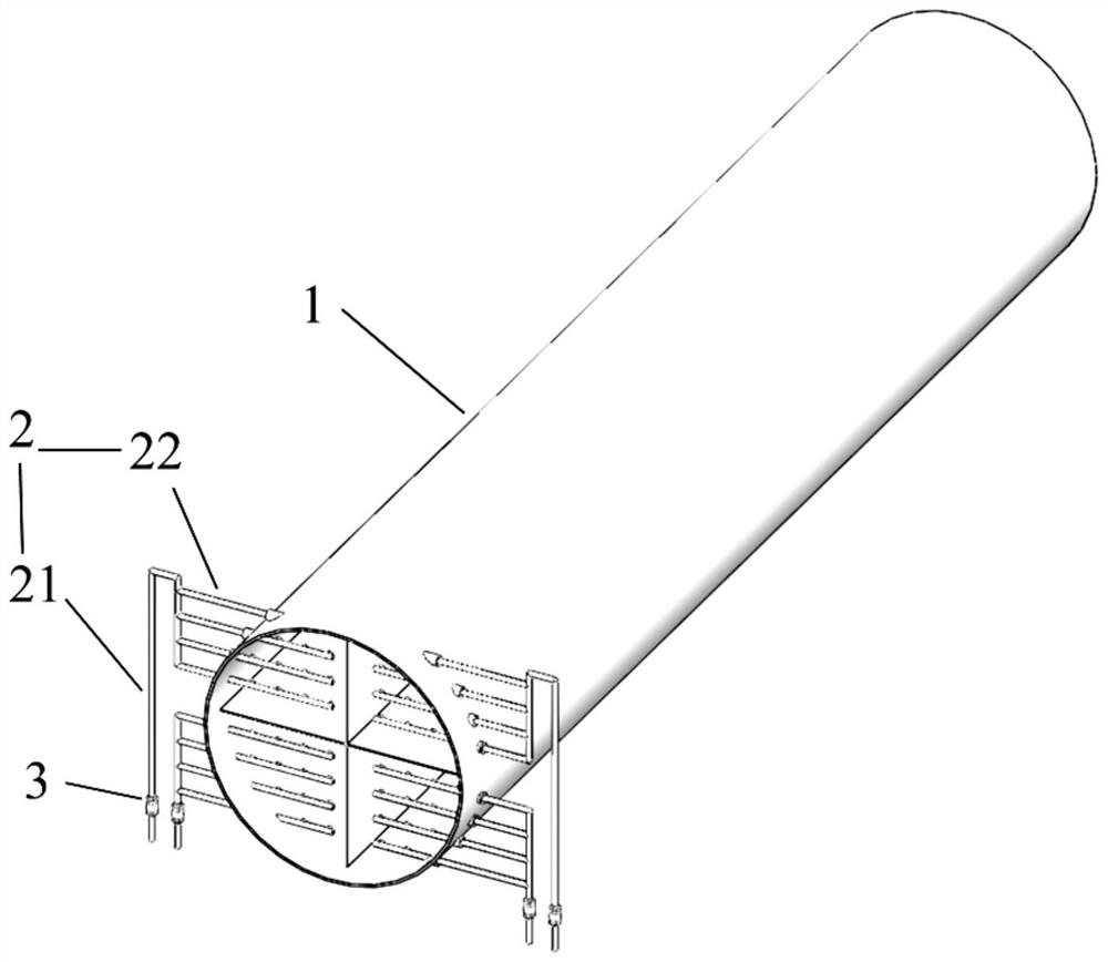
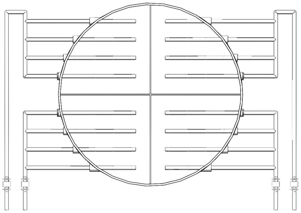
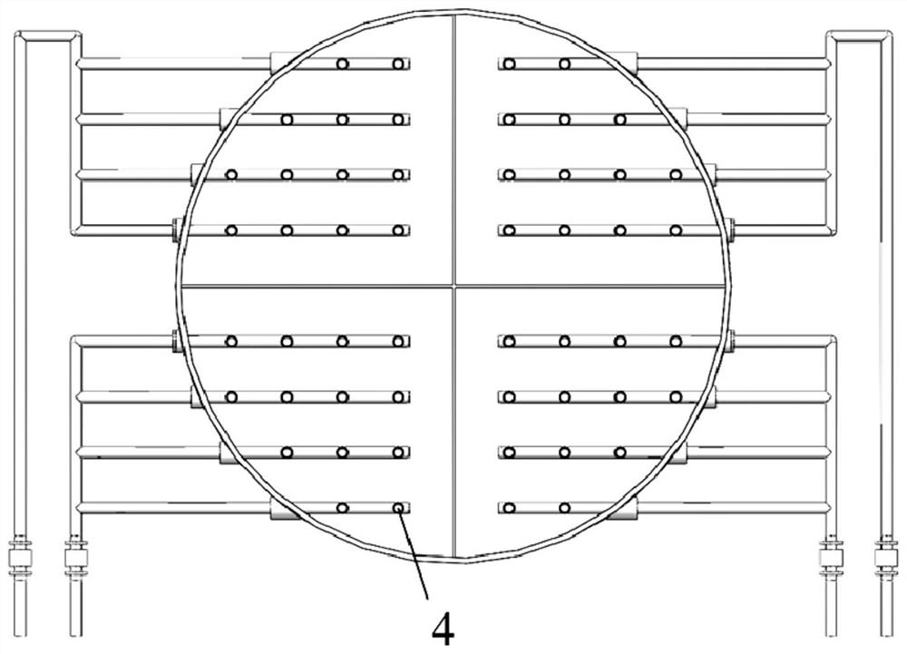
[0057] This embodiment provides an ozone distributor for zonal oxidation, the structural diagram of the ozone distributor is as follows figure 1 As shown, its front view, rear view and side view are as follows figure 2 , image 3 and Figure 4 As shown, it includes an ozone distributor main body 1 and an ozone delivery pipeline 2. The ozone distributor main body 1 is longitudinally divided into 4 distribution areas by a partition, each distribution area corresponds to a group of ozone delivery pipelines 2, and the ozone delivery pipeline 2 is set at one end of the main body 1 of the ozone distributor.

[0058] Wherein, one group of ozone delivery pipelines 2 includes a delivery main pipe 21 and a plurality of delivery branch pipes 22, the delivery main pipe 21 is provided with a flow regulating device 3, and the delivery branch pipe 22 is provided with a nozzle 4; The distances are equal, and the nozzles 4 are arranged on the conveying branch pipe 22 at equal intervals.

...

Embodiment 2

[0063] This embodiment provides an ozone distributor for zone oxidation. The ozone distributor refers to the ozone distributor in Example 1, the difference is that the reaction temperature is 90°C, the residence time of flue gas is 2s, and the flue gas in different distribution areas is mixed. The contact time is 1s.

Embodiment 3

[0065] This embodiment provides an ozone distributor for zone oxidation. The ozone distributor refers to the ozone distributor in Example 1. The difference is that the reaction temperature is 120°C, the residence time of the flue gas is 1s, and the flue gas in different distribution areas is mixed. The contact time is 0.75s.


PUM


Abstract

The invention discloses a zoning oxidation ozone distributor, and an arrangement mode and applications thereof. The zoning oxidation ozone distributor comprises an ozone distributor main body and ozone convey pipelines; the ozone distributor main body is longitudinally divided into a plurality of distribution zones by separating plates; a group of ozone convey pipelines is arranged in each distribution zone; and the ozone convey pipelines are arranged on one end of the ozone distributor main body. The zoning oxidation ozone distributor comprises a plurality of oxidation zones, ozone local excess supply is realized at conditions that the total ratio of ozone to NOx is relatively low, orientation increasing of the ratio of easily absorbable N2O5 in oxidation products is achieved, and flue gas denitration efficiency is increased; and in addition, flue gas in the distribution zones is mixed to eliminate local unreacted ozone; the zoning oxidation ozone distributor is simple in design, andhigh in operationality, is capable of reducing denitration technology cost effectively, is obvious in engineering advantages, and is suitable for wide applications in the field of oxidation-absorptiondenitration technology.

Description

technical field [0001] The invention belongs to the technical field of gas purification, and relates to an ozone distributor for zone oxidation, its arrangement and application. Background technique [0002] Nitrogen oxides (NO x ) is a class of major air pollutants that form acid rain, photochemical smog and PM 2.5 One of the main factors of pollution. At present, my country's industrial sources of NO x Emissions accounted for NO x More than 70% of the total emissions, NO in industrial flue gas x The current emission control technologies mainly include selective catalytic reduction (SCR), activated carbon adsorption catalytic method and oxidation-absorption method. Among them, SCR is widely used in denitrification of coal-fired power plants, which requires a temperature window of 300-400 °C, and NO x In catalyst and NH 3 Reverted to N under the action of 2 , the denitrification efficiency can reach more than 90%; the activated carbon adsorption catalytic method util...

Claims


Application Information

Patent Timeline
Patent Type & Authority Patents(China)
IPC IPC(8): B01D53/76B01D53/56
CPCB01D53/56B01D53/76B01D2251/104B01D2258/0283
Inventor 朱廷钰王健徐文青
Owner INST OF PROCESS ENG CHINESE ACAD OF SCI
Learn More