Production technology of auto-suspension proppant

A production process and proppant technology, which is applied in the production process field of self-suspension proppant, can solve problems such as increased cost and environmental pollution, and achieve the effects of low equipment and energy consumption, short process time, and low coating temperature

Inactive Publication Date: 2019-01-11
CHONGQING CHANGJIANG RIVER MOLDING MATERIAL GRP
View PDF18 Cites 2 Cited by
  • Summary
  • Abstract
  • Description
  • Claims
  • Application Information

AI Technical Summary

Problems solved by technology

[0005] The purpose of the present invention is to provide a production process of self-suspending proppant to solve the problem that

Method used

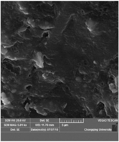
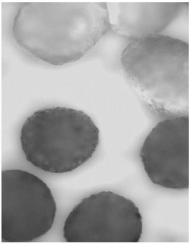

Image

  • Production technology of auto-suspension proppant
  • Production technology of auto-suspension proppant
  • Production technology of auto-suspension proppant

Examples


Example Embodiment

[0043] Example 1

[0044] Take the apparent density as 1.1g / cm 3 100 parts of ceramsite and quartz sand with a particle size of 20 / 40, heated to 180°C, pour the heated ceramsite and quartz sand into a bowl-shaped mixing casserole and stir, and add 1 part of epoxy resin after the temperature reaches 170-180°C Stir the resin and 0.25 parts of curing agent T31, add 5 parts of propylene glycol polymer and 0.01 part of dibutyltin dilaurate after the temperature reaches 110-130 ° C, add 0.005 parts of diethylene triamine and Stir the mixture of ethylenediamine, add 3.5 parts of isocyanate and stir when the temperature reaches 80-110°C, and take out the pot when the temperature reaches 40-70°C.

Example Embodiment

[0045] Example 2

[0046] Take the apparent density as 1.6g / cm 3 , The particle size is 30 / 50 ceramsite and quartz sand, a total of 100 parts, heat the mixture of ceramsite and quartz sand to 200 ° C, pour it into a bowl-shaped mixing casserole, and add 5 parts of phenolic formaldehyde when the temperature reaches 180-190 ° C Stir the resin, when the temperature reaches 160-170°C, add 1.5 parts of hexamethylenetetramine and stir, when the temperature reaches 100-120°C, add 4 parts of ethylene glycol polymer and stir, when the temperature reaches 80-100°C Add 0.04 parts of dibutyltin dilaurate and stir, add 2.3 parts of isocyanate when the temperature reaches 80-100°C and stir, and take out the pot when the temperature reaches 40-70°C.

Example Embodiment

[0047] Example 3

[0048] Take the apparent density as 2.2g / cm 3 100 parts of ceramsite and quartz sand with a particle size of 40 / 70. Heat the mixture of ceramsite and quartz sand to 230°C and pour it into a bowl-shaped mixing casserole. After the temperature reaches 190-230°C, add 6 parts of epoxy Stir the ester resin, add 2.7 parts of curing agent T31 when the temperature reaches 160-170°C and stir, add 3 parts of ethylene glycol polymer and stir when the temperature reaches 160-170°C, add Stir 0.03 parts of dibutyltin dilaurate, add 0.6 parts of ethylamine and stir when the temperature reaches 100-110°C, add 2 parts of diphenyl diisocyanate and stir when the temperature reaches 80-100°C, and stir when the temperature reaches 40-70 Take out the pot between ℃.


PUM

PropertyMeasurementUnit
Apparent densityaaaaaaaaaa
Densityaaaaaaaaaa

Abstract

The invention belongs to the technical field of oil and gas field exploitation, and concretely discloses a production technology of an auto-suspension proppant. The technology comprises the followingsteps: (1) heating ceramsite and quartz sands, with an apparent density of 1.1-2.65 g/cm<3>, to 80-230 DEG C, and performing stirring at a rotating speed of 60-90 r/min; (2) adding resin and a curingagent to ceramsite and quartz sands obtained in step (1) after the temperature reaches 150-230 DEG C, and performing stirring to form an inner coating layer, wherein the use amount of isocyanate is 45-75% of the use amount of polyol resin, and the hydroxyl equivalent of the polyol resin is 60-300; (3) adding the polyol resin, a catalyst, the isocyanate and an amine compound to a mixture obtained in step (2) after the temperature reaches 60-130 DEG C, and performing stirring to form an outer coating layer; and (4) discharging the obtained material after the temperature reaches 40-70 DEG C in order to obtain the auto-suspension proppant. The technology is mainly used for preparing the auto-suspension proppant, and solves the problems of cost increase and environment pollution caused by addition of a gelling agent needed by proppants used in clear water.

Description

technical field [0001] The invention belongs to the technical field of oil and gas field exploitation, and specifically discloses a production process of a self-suspending proppant. Background technique [0002] The innovation and development of conventional and unconventional oil and gas exploitation technologies in modern times have formed a normal technical specification for systematic hydraulic fracturing. The base mixed liquid is sent into the ground to create a variety of fractures of different sizes, widely distributed, and deep into the reservoir, and the obtained reservoir fractures are kept in an unclosed state to bring about the interconnection of the reservoir and the production pipeline to achieve the goal of reservoir stimulation. A technology system for increasing production. As a crucial technical method in this technical system, when the obtained reservoir fractures remain unclosed, it is necessary to fill the fractures with a proppant that can sustainably ...

Claims


Application Information

Patent Timeline
IPC IPC(8): C09K8/80
CPCC09K8/805
Inventor 熊帆熊鹰王正力陈秋庆
Owner CHONGQING CHANGJIANG RIVER MOLDING MATERIAL GRP
Why Eureka
Try Eureka