
Basement bottom plate structure high in floating and cracking resistance and design method thereof

A technology of basement floor and design method, which is applied in the directions of underwater structures, infrastructure engineering, building construction, etc., can solve the problems of reducing the service life of the floor structure, difficult to permanently repair, increasing investment, etc., so as to reduce the tensile stress. and shear stress, thickness and reinforcement ratio reduction, prolonging the service life effect

Active Publication Date: 2019-01-11
SOUTHWEST JIAOTONG UNIV
View PDF2 Cites 6 Cited by
  • Summary
  • Abstract
  • Description
  • Claims
  • Application Information

AI Technical Summary

Problems solved by technology

[0006] (2) Under the influence of factors such as the construction of underground rail transit and the development of underground space, it is more difficult to evaluate the groundwater level and its changes, the risk of the evaluation conclusion increases, and the reliability and safety of the anti-floating design of the basement floor are reduced, which is the cause of cracking and leakage of the basement floor Hidden dangers that cannot be predicted
[0007] (3) For high groundwater anti-floating head, increase the thickness of the basement floor of the building. In addition to the increase in investment, the difficulty of construction will increase. Construction joints and temperature cracks are unavoidable. Such cracks become channels and hidden dangers of water leakage, and it is difficult to permanently sex repair
[0008] (4) After temperature cracks, construction cracks, and initial structural cracks form water seepage, the reinforcement of the basement floor will be corroded at an accelerated rate, forming "initial cracks in the floor—water seepage through cracks—corrosion of steel bars and corrosion of concrete—widening of cracks—more serious water seepage in cracks" The vicious circle, which ultimately reduces the service life of the base plate structure

Method used


Image

  • Basement bottom plate structure high in floating and cracking resistance and design method thereof
  • Basement bottom plate structure high in floating and cracking resistance and design method thereof
  • Basement bottom plate structure high in floating and cracking resistance and design method thereof

Examples


Embodiment Construction

[0040] In order to make the object, technical solution and advantages of the present invention clearer, the present invention will be further described below in conjunction with the accompanying drawings and specific embodiments. It should be pointed out that the directional terms and order terms mentioned in the following embodiments, such as "upper", "lower", "front", "back", "left", "right", etc., are only referring to the accompanying drawings. Direction, therefore, the use of directional terms is for illustration and not for limitation of the invention.

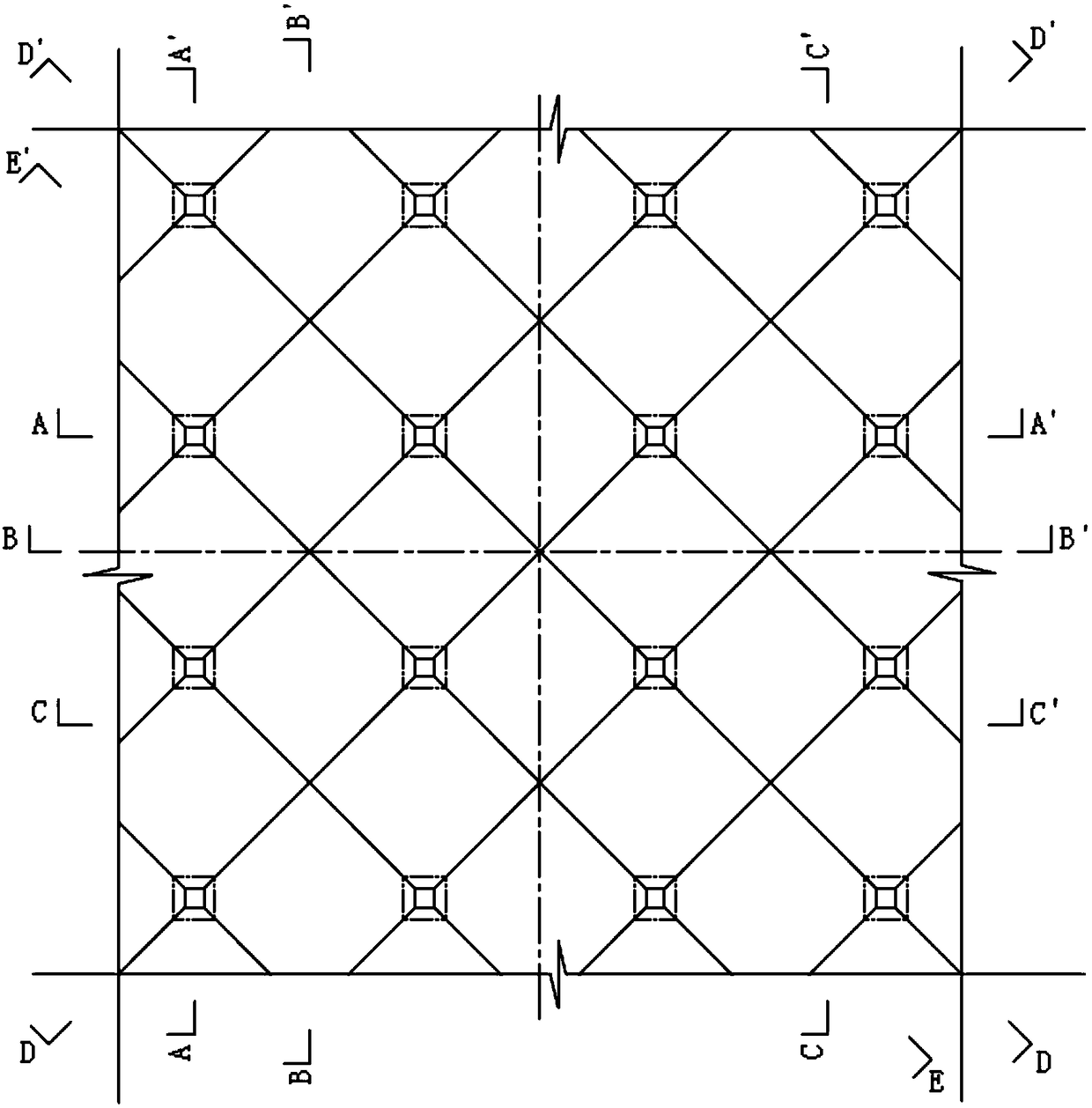
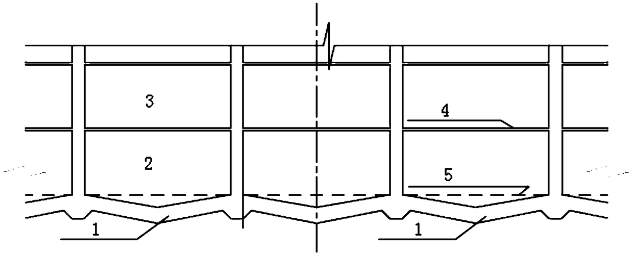
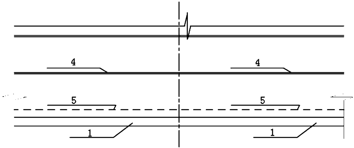
[0041] Such as Figure 1-11 As shown, in this embodiment, taking two-way 10m and other column center distances as an example, the basement floor structure with high anti-floating and crack resistance provided by the present invention is shown. The part is the part between four adjacent columns that can form a square on the basement floor. It is worth noting that in other cases (such as irregular column center distance,...


PUM


Abstract

The invention discloses a basement bottom plate structure high in floating and cracking resistance and a design method thereof. The basement bottom plate structure is of an inverted-pyramid-shaped space structure formed by subsidence of the position, between two adjacent columns, of a bottom plate. The design method of the basement bottom plate structure comprises the steps of determination of thedistance between every two adjacent columns of a building, determination of the subsidence height of the position, between the adjacent columns, of the bottom plate, determination of the subsidence form of the position, between the adjacent columns, of the bottom plate, determination of integral basement bottom plate layout, building of a basement bottom plate structure model, calculating of theinternal force of the basement bottom plate structure, reinforcing and structure chart drawing of the basement bottom plate structure, construction of the basement bottom plate, and the like. The basement bottom plate structure can bear large groundwater pressure and has high cracking resistance, permeation resistance and floating resistance. According to the design method of the basement bottom plate structure, the basement bottom plate structure high in floating and cracking resistance meeting the actual requirements can be designed according to different application projects, and the stepsare simple and high in operability.

Description

technical field [0001] The invention belongs to a special reinforced concrete structure, and in particular relates to a basement floor structure with high anti-floating and anti-crack performance and a design method thereof. Background technique [0002] At present, the hydrogeological conditions of construction sites are becoming more and more complex, and the groundwater level is affected by many factors such as the change of recharge in wet seasons and dry seasons and environmental underground engineering activities; due to the requirements of building height on foundation depth and underground The full development and utilization of space resources requires that the design of building foundations be deeper and deeper, and the floating force of groundwater on the foundation floor increases sharply, and the situation of exceeding 200kPa is almost normal; in order to improve the utilization of building space, reduce the underground building Difficulty in the layout of space...

Claims


Application Information

Patent Timeline
Patent Type & Authority Applications(China)
IPC IPC(8): E02D29/045E02D31/12E04B1/00
Inventor 邓荣贵李兴洲胡敏文琪鑫潘玉杰董玲李凯甜孙怡王园园
Owner SOUTHWEST JIAOTONG UNIV
Learn More