A device for low-energy ignition initiation detonation wave

A low-energy, detonation wave technology, used in jet propulsion, intermittent injection, machines/engines, etc., can solve problems such as limiting the working frequency and performance of PDE, reducing engine efficiency, limiting engineering applications, etc., to improve the maximum working frequency, improving combustion efficiency, avoiding the effect of flow loss

Active Publication Date: 2020-09-01
NORTHWESTERN POLYTECHNICAL UNIV
View PDF6 Cites 0 Cited by
  • Summary
  • Abstract
  • Description
  • Claims
  • Application Information

AI Technical Summary

Problems solved by technology

Among them, it takes a long time and distance to initiate the detonation wave with the DDT method. If a DDT enhancement device such as a Shchelkin screw is used, it will inevitably cause certain obstacles to the filling of the unburned mixture and the discharge of the burned mixture, increasing the Flow loss reduces the efficiency of the engine, limiting the improvement of PDE operating frequency and performance
If a conventional pre-explosion tube is used to detonate, it also requires a long axial distance, and the liquid fuel will cause serious wall attachment in the pre-explosion tube with a small inner diameter, and the work efficiency is low, which limits the engineering application of this method

Method used


Image

  • A device for low-energy ignition initiation detonation wave
  • A device for low-energy ignition initiation detonation wave
  • A device for low-energy ignition initiation detonation wave

Examples


Embodiment Construction

[0022] Below in conjunction with specific embodiment, accompanying drawing, the present invention will be further described:

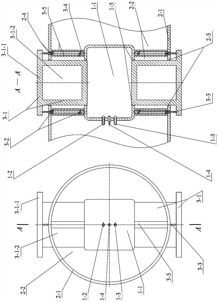
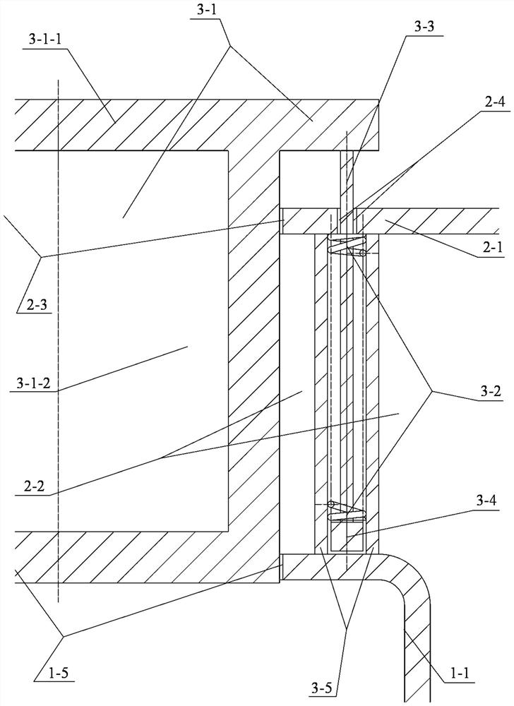
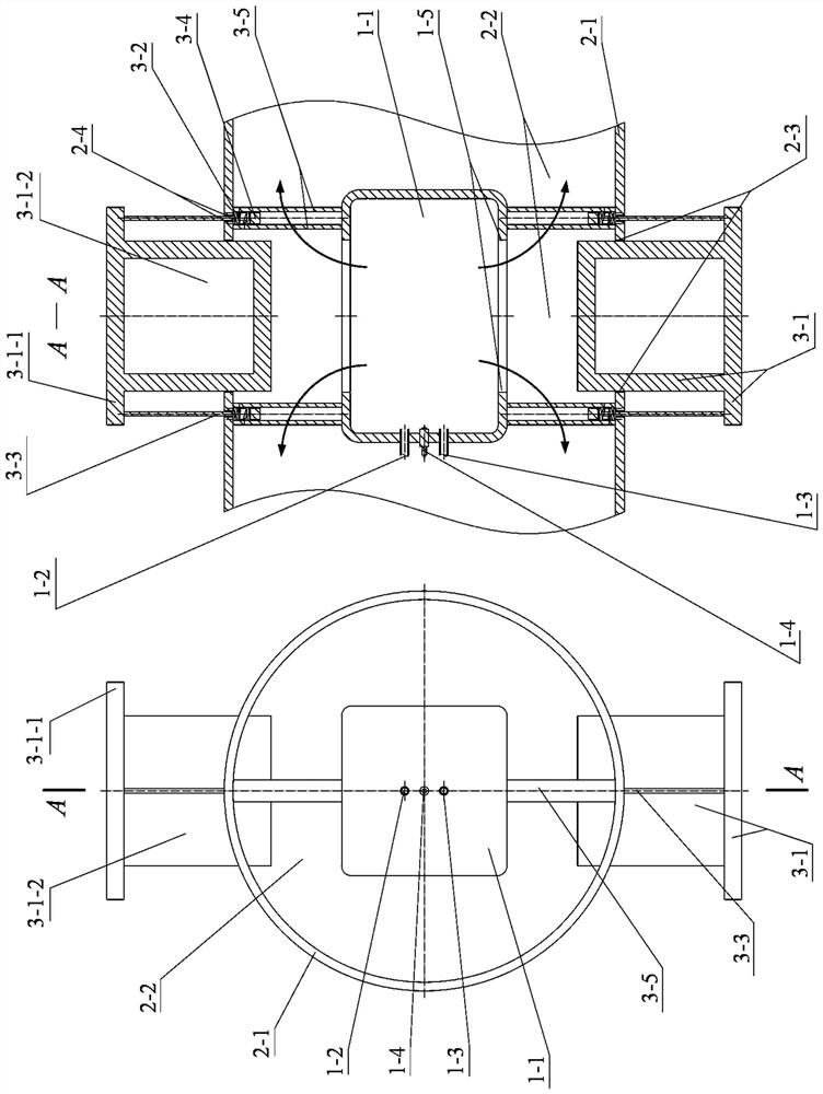
[0023] Specific examples figure 1 , figure 2 , image 3 and Figure 4 As shown, it consists of a pre-detonation chamber, a main detonation chamber and a piston spring actuation system. Wherein, the pre-explosion chamber is composed of a pre-explosion chamber cavity 1-1, an oxygen injection device 1-2, an explosive fuel injection device 1-3, and a low-energy pulse igniter 1-4; the pre-explosion chamber cavity 1 -1 is approximately a regular quadrangular prism, and the ratio of the height of the regular quadrangular prism to the side length of the square at the bottom (similar to the aspect ratio of the pre-explosion tube) is between 1:1 and 2:1; oxygen injection device 1-2, easy The detonation fuel injection device 1-3 and the low-energy pulse igniter 1-4 are installed on the head wall of the pre-detonation chamber cavity 1-1; the upper and lower w...


PUM


Abstract

The invention provides a device for igniting detonation waves at low energies. The device comprises a pre-detonation chamber, a main detonation chamber and a piston spring actuation system. The pre-explosion chamber is composed of a cavity, an oxygen and explosive fuel injection device and a low-energy pulse igniter. Two drainage holes are formed in the wall face of the pre-explosion chamber. Themain detonation chamber surrounds the pre-detonation chamber, and two piston actuating holes are formed in the wall face of the main detonation chamber, corresponding to the positions of the drainageholes and having the same aperture; and the piston spring actuation system is arranged on the outside of the drainage holes and consists of a piston, a spring, a connecting post, a limit block and a protective sleeve, and the piston moves up and down in translation by clinging to the hole walls of the drainage holes and the piston actuation holes. According to the invention, the communication andisolation between the pre-detonation chamber and the main detonation chamber are controlled by adjusting the relative magnitude of the pressure difference between the inner and outer sides of the piston and the spring force. The detonation waves generated by low energy ignition of pure oxygen and explosive fuel in the pre-detonation chamber are transmitted into the main detonation chamber throughthe drainage holes which are opened after the piston moves upward, so as to initiate the detonation waves in the explosive mixture of the main detonation chamber.

Description

technical field [0001] The invention relates to the technical field of detonation engines, in particular to a low-energy ignition initiation detonation wave device. Background technique [0002] Pulse detonation engine (Pulse Detonation Engine, referred to as PDE) is a power device that uses high-temperature and high-pressure gas generated by pulse detonation waves to obtain thrust. The short-distance, fast-starting detonation wave can increase the operating frequency of the PDE, thereby improving performance; at the same time, it can also shorten the axial length of the PDE detonation chamber, thereby increasing the thrust-to-weight ratio. Ignition with low energy to generate a frequency-controllable and fully developed two-phase pulse detonation wave in a very short distance is an important key technology of PDE. [0003] There are usually two ways to initiate a detonation wave: direct detonation and indirect detonation. Direct detonation often requires huge detonation e...

Claims


Application Information

Patent Timeline
Patent Type & Authority Patents(China)
IPC IPC(8): F02K7/02F02K5/02
CPCF02K5/02F02K7/02
Inventor 范玮孙田雨李清安董荣晓裴一哲
Owner NORTHWESTERN POLYTECHNICAL UNIV
Why Eureka
Try Eureka