A testing method for free radical photoproducts

A test method and free radical technology, applied in the field of spectrochemistry, can solve the problems of inability to form, limited size, turbulent ion beam flow, etc., and achieve the effects of reducing loss, reducing pumping speed, and reducing device volume

Active Publication Date: 2019-01-11
JINHUA VOCATIONAL TECH COLLEGE
View PDF15 Cites 0 Cited by
  • Summary
  • Abstract
  • Description
  • Claims
  • Application Information

AI Technical Summary

Problems solved by technology

[0002] Devices for studying photoreaction products such as molecules or free radicals usually study the ion beam current of the molecule to be measured in a vacuum environment, and usually need to make the solution containing the sample to be tested atomized and then enter the vacuum environment. The first defect of the prior art: existing Some devices in the technology use the electrospray method to atomize the solution containing the sample to be tested, which has certain requirements for the solvent in the solution, that is, it must be a polar solution, and a high voltage must be applied to the liquid when the electrospray is working, which limits The type of sample that the electrospray method is suitable for; the second defect of the prior art: some devices in the prior art make the liquid spray out and form droplets by directly applying pressure to the liquid, and the size of the droplets produced by this method is limited Due to the inner diameter of the droplet nozzle, it is impossible to form smaller droplets; the third defect of the prior art: in the ion beam current testing device in the prior art, a multi-stage vacuum pump group is usually used to evacuate different chambers. The vacuum difference between the cavities will cause the ion beam to form a turbulent flow, thereby affecting the final detection efficiency. The free radical light product test method can solve the problem

Method used


Image

  • A testing method for free radical photoproducts
  • A testing method for free radical photoproducts
  • A testing method for free radical photoproducts

Examples


Embodiment Construction

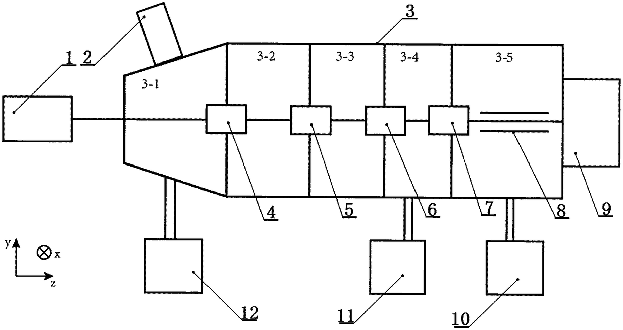
[0025] like figure 1It is a schematic diagram of the present invention, xyz is a three-dimensional space coordinate system, mainly including a laser (1), a droplet injector (2), a vacuum chamber (3), an ion beamer I (4), and an ion beamer II (5) , ion beamer III (6), ion beamer IV (7), quadrupole rod (8), detector (9), vacuum pump group I (10), vacuum pump group II (11), vacuum pump group III ( 12) and an ionization device, the vacuum chamber (3) has a starting end and an end, and in the vacuum chamber (3), there are a sample injection chamber (3-1) and a drift chamber 1 (3-2) sequentially from the starting end to the end ), drift chamber II (3-3), buffer chamber (3-4) and collision chamber (3-5), the sample injection chamber (3-1), buffer chamber (3-4) and collision chamber (3 -5) Vacuum pump group III (12), vacuum pump group II (11) and vacuum pump group I (10) are respectively connected; the ion buncher I (4), ion buncher II (5), ion buncher Device III (6), ion beamer IV ...


PUM

PropertyMeasurementUnit
thicknessaaaaaaaaaa

Abstract

The invention relates to the field of spectrochemistry and provides a testing method for free radical photoproduct which is features that helium gas is pas into drift chamber II, nitrogen gas is passed into buffer chamber and flow rate is 80SCCM. Controlling a mass flow controller, wherein the sample solution to be tested is injected into the reservoir at a flow rate of 0.02 ml / min to 0.2 ml / min;Drive I and Drive II are turned on, respectively, and there are two modes of operation; a liquid drop enter a vacuum chamber and form an ion pack, and then forms an ion beam current, and that ion beamcurrent reaches an ion beam concentrator II through an ion beam concentrator I; adjusting the potentials applied to the extraction grid, the trapping grid and the incoming grid, respectively, so thata portion of the ions in the ion beam current are trapped in the section IV of the ion beam concentrator II. The laser beam enters into the section IV and irradiates the ions, causing a photoreactionand producing a photoproduct. The potential is adjusted so that charged particles in the photoproduct are emitted from the section V of the ion buncher II and then passed through the ion buncher III,the ion buncher IV and the quadrupole in turn before finally entering the detector.

Description

technical field [0001] The invention relates to the field of spectrochemistry, in particular to a free radical light product testing method which has a special sample solution atomization method and can test the photoreaction products of many kinds of free radicals. Background technique [0002] Devices for studying photoreaction products such as molecules or free radicals usually study the ion beam current of the molecule to be measured in a vacuum environment, and usually need to make the solution containing the sample to be tested atomized and then enter the vacuum environment. The first defect of the prior art: existing Some devices in the technology use the electrospray method to atomize the solution containing the sample to be tested, which has certain requirements for the solvent in the solution, that is, it must be a polar solution, and a high voltage must be applied to the liquid when the electrospray is working, which limits The type of sample that the electrospray...

Claims


Application Information

Patent Timeline
Patent Type & Authority Applications(China)
IPC IPC(8): H01J49/00G01N21/76
CPCH01J49/004G01N21/76
Inventor 张向平李凡赵永建
Owner JINHUA VOCATIONAL TECH COLLEGE
Why Eureka
Try Eureka