Fm-cw radar and method for generating fm-cw signal

A FM-CW and radar technology, applied in the direction of reflection/re-radiation of radio waves, use of re-radiation, measurement devices, etc., can solve problems such as disadvantages, reduce mass production inspection time, and cannot cope with changes in VCO characteristics, and achieve coping characteristics. effect of change

Active Publication Date: 2019-01-11
MITSUBISHI ELECTRIC CORP
View PDF7 Cites 2 Cited by
  • Summary
  • Abstract
  • Description
  • Claims
  • Application Information

AI Technical Summary

Problems solved by technology

[0004] On the other hand, in the transceiver module constituting the FM-CW radar, due to the variation and temperature characteristics of individual differences in the Voltage Control Oscillator (Voltage Control Oscillator: hereinafter referred to as "VCO"), it is necessary to adjust it in the shipment inspection process operation, which is not conducive to reducing the inspection time during mass production
In addition, since there is no feedback control after shipment, there is also a problem that it cannot cope with changes in VCO characteristics due to aging over time.

Method used


Image

  • Fm-cw radar and method for generating fm-cw signal
  • Fm-cw radar and method for generating fm-cw signal
  • Fm-cw radar and method for generating fm-cw signal

Examples


Embodiment approach 1

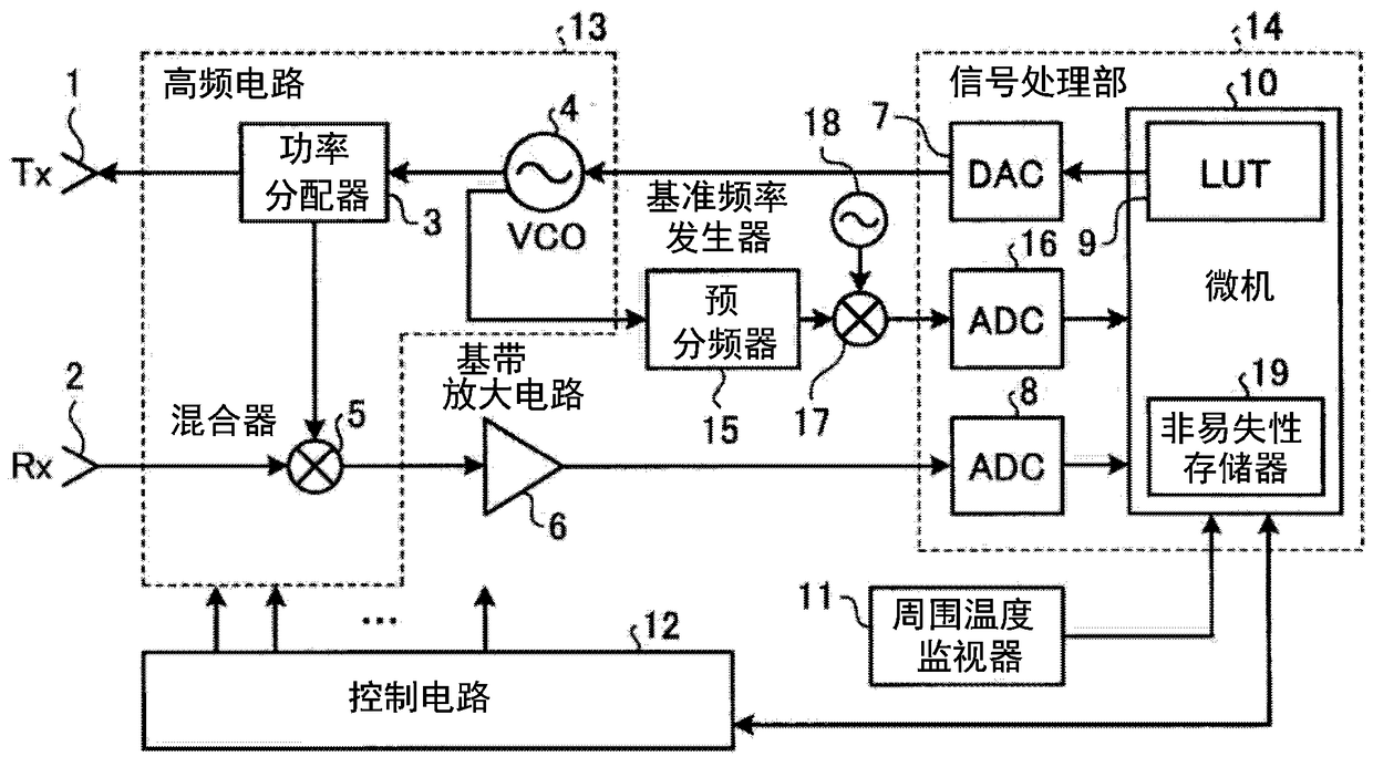
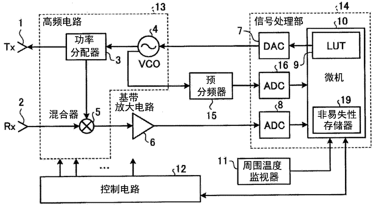
[0036] figure 1 It is a block diagram showing the configuration of the FM-CW radar according to the first embodiment. The FM-CW radar involved in Embodiment 1 is an FM-CW radar using frequency modulation based on the FM-CW method, such as figure 1 As shown, it is composed mainly of the following structural elements, namely: a high-frequency circuit 13, which radiates a transmission signal as an electric wave to space via a transmission antenna 1 (Tx), and transmits a signal to the air via a reception antenna 2 (Rx). The reflected wave from the target object of the transmitted radio wave is received; the signal processing unit 14 converts the analog signal output from the high-frequency circuit 13 into a digital signal, and calculates the distance to the target object and the target object The speed is detected, and if necessary, the orientation of the target object is detected; and the control circuit 12 controls various control voltages supplied to the high frequency circuit...

Embodiment approach 2

[0116] In Embodiment 1, calculation processing in the case of approximating the V-f curve using a quadratic function has been described as correction processing using polynomial approximation. That is, Embodiment 1 is a method of directly calculating a voltage initial value using a quadratic function. On the other hand, Embodiment 2 does not directly calculate the initial value of the voltage, but proposes a method of using a solution based on an iterative method using an approximate solution, thereby even using a polynomial with a third degree or higher or other methods including an exponential function. The function can also approximate the V-f curve.

[0117] Hereinafter, in this embodiment, as an example of functions other than quadratic functions, refer to Figure 8 to Figure 12 The calculation processing when the cubic function is used will be described. Figure 8 It is a flowchart showing calculation processing of an initial frequency value and an initial voltage valu...

Embodiment approach 3

[0145] In Embodiment 1, the embodiment in which the update processing of LUT 9 is performed by combining the frequency calculation processing using phase calculation and the correction processing using polynomial approximation was described. However, in Embodiment 3, the correction using time error calculation A description will be given of an embodiment in which the processing is replaced with the second and subsequent update processing of the LUT9. In addition, the basic structure is the same as figure 1 or figure 2 The structure of Embodiment 1 shown is the same or equivalent, and the description of the specific structure will be omitted.

[0146] Next, refer to Figure 13 and Figure 14 , the main parts of the FM-CW radar according to Embodiment 3 will be described. Figure 13 It is a flowchart showing the flow of correction processing using time error calculation in the microcomputer 10 . Figure 14 This is a diagram for explaining the concept of "correction process...


PUM


Abstract

In FM-CW radar, a high-frequency circuit 13 for receiving reflected waves from a target object and a signal processing unit 14 for converting an analog signal generated by the high-frequency circuit 13 to a digital signal and detecting at least the distance to the target object and the speed of the target object are configured. The high-frequency circuit 13 is provided with a VCO 4 for receiving amodulation voltage from the signal processing unit 14 and generating a frequency-modulated high-frequency signal. The signal processing unit 14 is provided with a LUT 9 in which initial values of modulation control data are stored. The signal processing unit 14 applies a default chirp having a linear characteristic, calculates a frequency initial value and a voltage initial value from a voltage frequency characteristic appearing in response to application of the default chirp, generates time data using the calculation result, and updates the data stored in the LUT 9 through use of the generated time data.

Description

technical field [0001] The present invention relates to an FM-CW radar utilizing frequency modulation based on an FM-CW (Frequency Modulated Continuous Waves) method and a method of generating an FM-CW signal transmitted from the FM-CW radar. Background technique [0002] The structure of FM-CW radar is relatively simple, the frequency band for processing in the baseband is a lower frequency band, and the signal processing is relatively easy. Due to these reasons, in recent years, collision avoidance in the millimeter wave frequency band aimed at cost reduction Widely used in radar etc. [0003] In the FM-CW method, an up chirp signal (Up chirp signal) that changes the transmission frequency from low frequency to high frequency and a down chirp signal (Down chirp signal) that changes the transmission frequency from high frequency to low frequency are used. The sum of the peak frequencies of the beat signals obtained from each chirp signal and the difference between the peak...

Claims


Application Information

Patent Timeline
Patent Type & Authority Applications(China)
IPC IPC(8): G01S13/34G01S7/40
CPCG01S7/35G01S13/345G01S7/4008G01S7/358G01S7/40G01S13/34
Inventor 仓茂和纪
Owner MITSUBISHI ELECTRIC CORP
Why Eureka
Try Eureka