Optical fiber ring for optical fiber gyro and optical fiber ring processing method

A fiber optic gyroscope and processing method technology, which is applied to Sagnac effect gyroscopes, gyroscopes/steering sensing equipment, measuring devices, etc., can solve the problem of poor Shupe error suppression performance, large error signal, and fiber can not be fully wound, etc. problem, to achieve the effect of small temperature error and reduced influence

Pending Publication Date: 2019-01-15
HUNAN AEROSPACE ELECTROMECHANICAL EQUIP & SPECIAL MATERIAL INST
View PDF5 Cites 8 Cited by
  • Summary
  • Abstract
  • Description
  • Claims
  • Application Information

AI Technical Summary

Problems solved by technology

However, in the existing optical fiber sensitive ring structure, due to the influence of the optical fiber sensitive wrapping tooling or the uneven diameter of the optical fiber, it usually leads to the situation that the outermost two layers of optical fibers cannot be completely wound after the winding is completed, that is to say After winding, the number of fiber layers of the fiber ring cannot satisfy the integer multiple of 4, thus losing the superiority of the quadrupole symmetrical winding method, and the error signal is even larger than that of the bipolar symmetrical winding method, completely losing the advantages of the quadrupole symmetrical winding method Advantage, so the suppression performance of Shupe error is poor

Method used


Image

  • Optical fiber ring for optical fiber gyro and optical fiber ring processing method
  • Optical fiber ring for optical fiber gyro and optical fiber ring processing method
  • Optical fiber ring for optical fiber gyro and optical fiber ring processing method

Examples


Embodiment

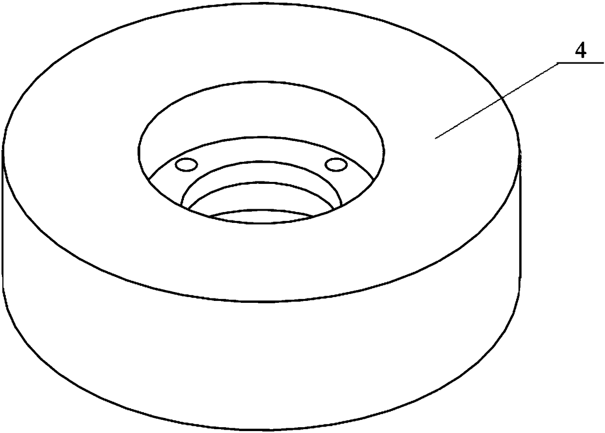
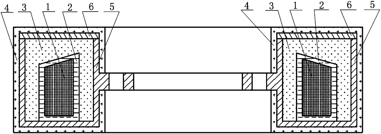
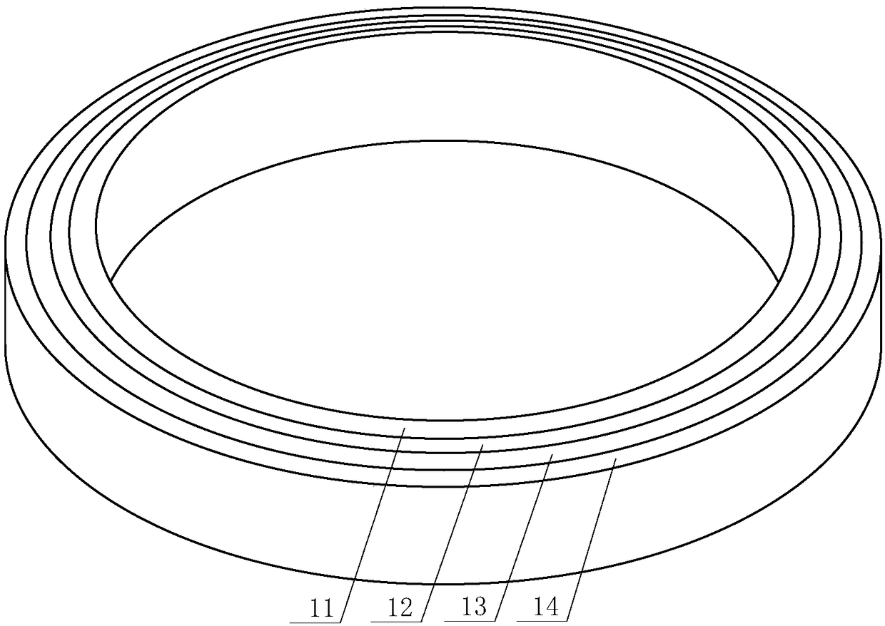
[0038] Such as figure 1 — Figure 7 As shown, the optical fiber ring of the present invention includes an optical fiber sensitive ring 1 , a magnetic shielding film 2 , a heat storage layer 3 , a magnetic shielding cover 6 , a magnetic shielding base 5 and a heat insulation layer 4 .

[0039] Such as figure 2As shown, the optical fiber sensitive ring 1, the magnetic shielding film 2, the heat storage layer 3, the magnetic shielding cover, and the heat insulation layer 4 are sequentially arranged from the inside to the outside; the magnetic shielding cover includes a magnetic shielding seat 5 and a Magnetic shielding cover 6; the magnetic shielding cover is an airtight structure, and the pigtail fiber of the optical fiber sensitive ring 1 passes through the magnetic shielding film 2 and the magnetic shielding cover successively and is connected with the Y waveguide pigtail fiber of the optical fiber gyroscope system; the heat storage layer 3 is made of heat storage material ...


PUM


Abstract

The invention provides an optical fiber ring for optical fiber gyros. The optical fiber ring comprises a optical fiber sensitive ring, a magnetic shielding film, a heat storage layer, a magnetic shielding case and a thermal insulation layer which are sequentially arranged from inside to outside. The magnetic shielding case comprises a magnetic shielding base and a magnetic shielding cover laminated on the magnetic shielding base. The magnetic shielding case is a closed structure. A pigtail of the optical fiber sensitive ring sequentially penetrates through the magnetic shielding film and the magnetic shielding case to be connected with a Y waveguide pigtail of an optical fiber gyro system. The heat storage layer is composed of a heat storage material. The invention further provides an optical fiber ring processing method. According to the optical fiber ring for optical fiber gyros and the optical fiber ring processing method, by adopting the wrapping method for the optical fiber sensitive ring as well as the heat storage layer and the heat insulation layer on the structure, the influence of the temperature on the fiber sensitive ring is reduced, and the gyro temperature performanceis improved. The magnetic shielding film and the magnetic shielding case are combined to form a double-layer magnetic shielding structure, so that the influence of the external magnetic field on theoptical fiber sensitive ring is effectively reduced, and the environment adaptability of the optical fiber ring on the temperature and the magnetic field is improved.

Description

technical field [0001] The invention relates to an optical fiber ring that eliminates the influence of the external environment, in particular to an optical fiber ring used for an optical fiber gyroscope and a processing method for the optical fiber ring, and belongs to the technical fields of optical measurement and optical fiber sensing. Especially the design and manufacture of an optical fiber ring for a fiber optic gyroscope. Background technique [0002] Fiber optic gyroscope is an optical sensor based on SAGNAC effect to measure angular velocity, and it is the second generation of optical gyroscope after laser gyroscope. It has been applied in many fields such as aircraft navigation, spacecraft guidance, satellite positioning, automobile guidance, intelligent robots, astronomical telescopes, aircraft and ship navigation, and weapon system control. [0003] As the core component of the fiber optic gyroscope, the optical fiber ring directly determines the performance of...

Claims


Application Information

Patent Timeline
Patent Type & Authority Applications(China)
IPC IPC(8): G01C19/72G01C25/00
CPCG01C19/721G01C25/00
Inventor 于中权岑礼君
Owner HUNAN AEROSPACE ELECTROMECHANICAL EQUIP & SPECIAL MATERIAL INST
Why Eureka
Try Eureka