A frequency reconfigurable sensing patch antenna

A technology of sensing stickers and chip antennas, which is applied to the structural connection of antennas, antenna grounding devices, and antenna grounding switches. Excellent performance and small size effect

Inactive Publication Date: 2019-01-15
苏州智汇云祥通信系统有限公司
View PDF10 Cites 4 Cited by
  • Summary
  • Abstract
  • Description
  • Claims
  • Application Information

AI Technical Summary

Problems solved by technology

[0003] In recent years, scholars at home and abroad have proposed a variety of frequency reconfigurable ante...

Method used


Image

  • A frequency reconfigurable sensing patch antenna
  • A frequency reconfigurable sensing patch antenna

Examples


Embodiment Construction

[0027] The principles and features of the present invention are described below in conjunction with the accompanying drawings, and the examples given are only used to explain the present invention, and are not intended to limit the scope of the present invention.

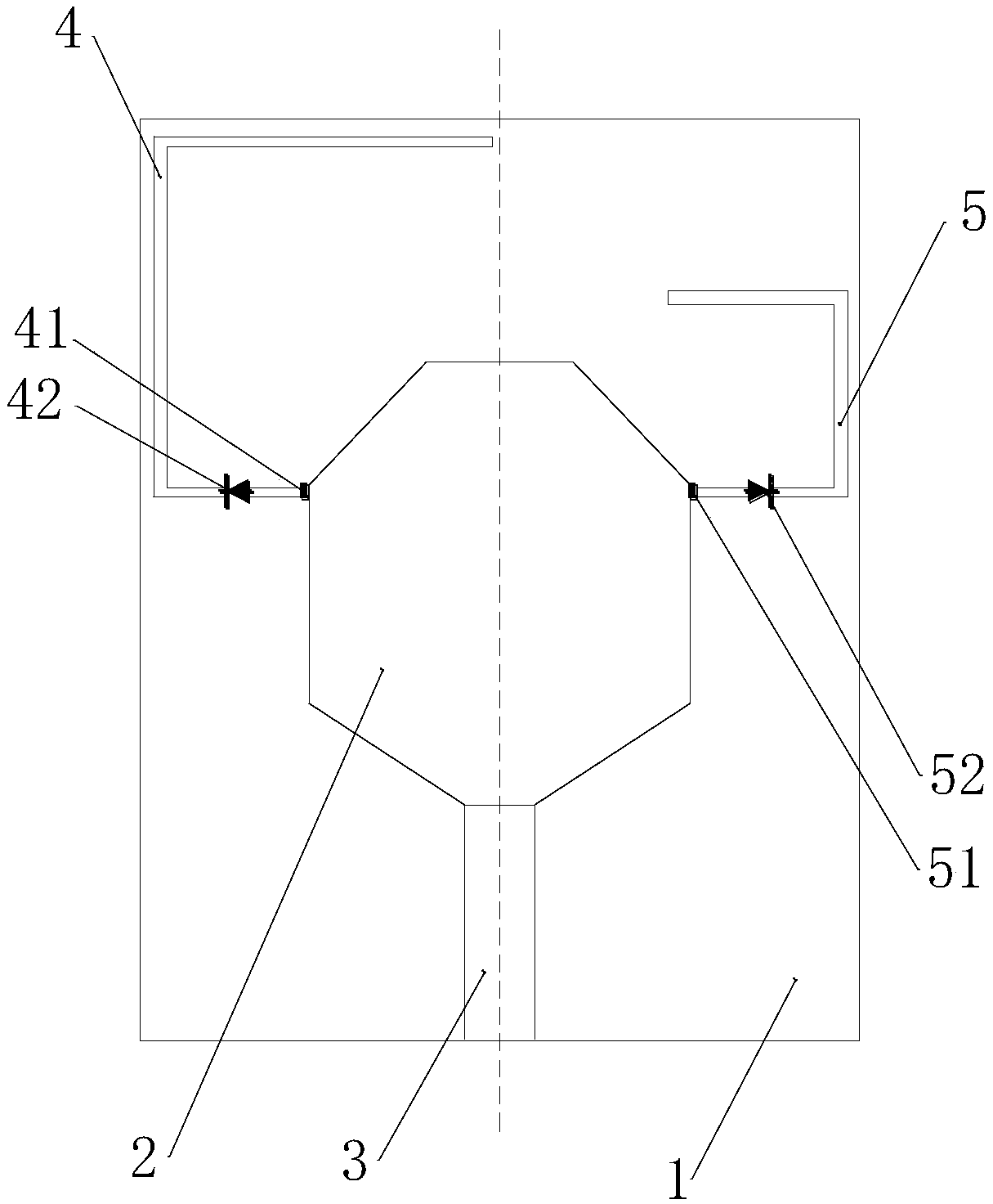
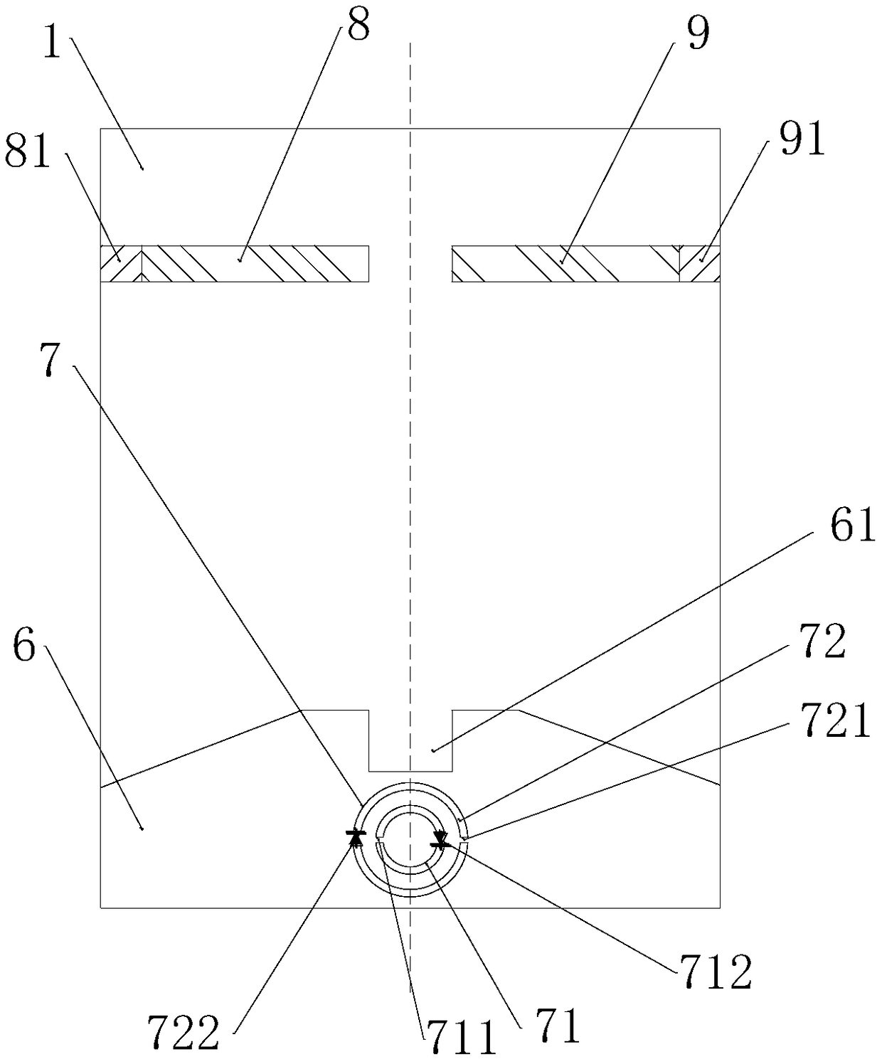
[0028] Such as figure 1 and figure 2 As shown, a frequency reconfigurable sensing patch antenna includes a microstrip feeder 3, a dielectric substrate 1, a radiation sheet 2 and a ground plate 6, the microstrip feeder 3 is connected to the radiation sheet 2, and Both the microstrip feeder 3 and the radiation sheet 2 are attached to the front of the dielectric substrate 1, the ground plate 6 is attached to the back of the dielectric substrate 1, and the ground plate 6 and the micro The tape feeder 3 is located at the same end of the dielectric substrate 1 .

[0029] The radiation sheet 2 is connected to the ground plate 6 through the microstrip feeder 3 .

[0030] The dielectric substrate 1, the radiation sheet 2...


PUM

PropertyMeasurementUnit
Thicknessaaaaaaaaaa

Abstract

A frequency reconfigurable sensing patch antenna include microstrip feeder, a dielectric substrate, a radiating sheet and a ground plane, wherein the microstrip feed line is connected with the radiating sheet, the microstrip feed line and the radiating sheet are all stuck on the front side of the dielectric substrate, the ground plane is stuck on the back side of the dielectric substrate, and theground plane and the microstrip feed line are located at the same end of the dielectric substrate; A first branch and a second branch are respectively arranged on the two sides of the radiation sheet,and the first branch and the second branch are respectively provided with a first capacitor and a second capacitor at the connection with the radiation sheet; The first branch and the second branch are respectively provided with a first diode and a second diode. The antenna of the invention has the advantages that the antenna is a patch structure, the volume is small, the structure is simple andreasonable, and the antenna frequency is changed by using the on or off states of the first diode and the second diode, thereby realizing the reconfigurable antenna frequency.

Description

technical field [0001] The invention relates to the technical field of optical communication antennas, in particular to a frequency reconfigurable sensing patch antenna. Background technique [0002] In recent years, with the development of wireless communication systems in the direction of high integration and multi-functionality, antennas, as the key components for receiving or sending signals in wireless communication systems, have gradually become a research hotspot in the field of antennas for their multi-functionality and tunability. Due to the above characteristics, reconfigurable antennas have gradually shown great application potential. Its excellent electrical characteristics, such as frequency tunable, polarization or pattern reconfigurable, etc., can well meet the requirements of highly integrated antennas. Multifunctional wireless communication system needs. [0003] In recent years, scholars at home and abroad have proposed a variety of frequency reconfigurabl...

Claims


Application Information

Patent Timeline
IPC IPC(8): H01Q1/38H01Q1/48H01Q1/50H01Q5/10H01Q5/28H01Q5/314H01Q5/321
CPCH01Q1/38H01Q1/48H01Q1/50H01Q5/10H01Q5/28H01Q5/314H01Q5/321
Inventor 王亚丽杨国民
Owner 苏州智汇云祥通信系统有限公司
Why Eureka
Try Eureka