A new energy system and Z-source DC-DC converter thereof

A DC-DC and converter technology, applied in the field of new energy systems and their Z-source DC-DC converters, can solve the problems of reduced efficiency, increased switching loss, large current ripple, etc., to reduce complexity and cost, Reduced conduction loss and simple control

Inactive Publication Date: 2019-01-15
GUANGDONG UNIV OF TECH
View PDF4 Cites 11 Cited by
  • Summary
  • Abstract
  • Description
  • Claims
  • Application Information

AI Technical Summary

Problems solved by technology

[0003] High-gain DC-DC converters used in the prior art often use cascaded DC-DC converters, specifically, please refer to figure 1 , figure 1 It is a structural schematic diagram of a traditional cascaded DC-DC converter. This type of converter is formed by cascading two or even multi-level boost circuits. On the one hand, the larger the duty cycle, the energy storage inductor in this type of converter It will reach magnetic saturation, and work in the current discontinuous mode (DCM mode), which will cause large current ripples and current peaks, making it difficult to design the control loop; in addit

Method used


Image

  • A new energy system and Z-source DC-DC converter thereof
  • A new energy system and Z-source DC-DC converter thereof
  • A new energy system and Z-source DC-DC converter thereof

Examples


Embodiment Construction

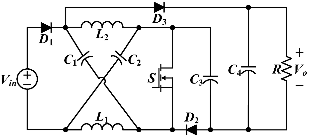
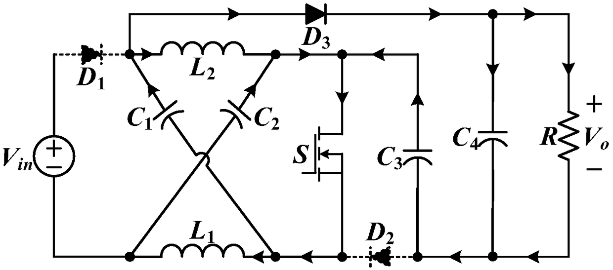
[0025] The core of the present invention is to provide a new energy system and its Z-source DC-DC converter to achieve high gain at a lower duty cycle without cascading to achieve high gain and reduce the complexity of the circuit structure and cost; in addition, it also reduces the conduction loss of the switch tube and improves the efficiency of the Z-source DC-DC converter; and because there is only one switch module in the Z-source DC-DC converter, the control is simple.

[0026] In order to make the purpose, technical solutions and advantages of the embodiments of the present invention clearer, the technical solutions in the embodiments of the present invention will be clearly and completely described below in conjunction with the drawings in the embodiments of the present invention. Obviously, the described embodiments It is a part of embodiments of the present invention, but not all embodiments. Based on the embodiments of the present invention, all other embodiments ob...


PUM


Abstract

The invention discloses a Z source DC- DC convert includes a switch module, a first diode, a second diode, a third diode, a first inductor, a second inductor, a first capacitor, a second capacitor, athird capacitor, and a fourth capacitor. As can be seen, the Z source DC-DC converter gain can achieve high gain at low duty cycle. While the cascade is not needed to realize high gain, and the complexity and cost of the circuit structure are reduced; In addition, the on-loss of the switching transistor is reduced, and the Z-source DC-DC converter efficiency; And there is only one switch modulein the Z source DC -DC converter , which is easy to control. The invention also provides a new energy source system, which comprises a Z-source DC- DC convert has that same beneficial effect.

Description

technical field [0001] The invention relates to the technical field of converters, in particular to a new energy system and a Z-source DC-DC converter thereof. Background technique [0002] With the increasingly serious energy crisis and environmental pollution, renewable energy is becoming more and more important and common worldwide, especially distributed power generation systems based on renewable energy, such as fuel cells, photovoltaic panels, etc. Due to the low voltage characteristics of photovoltaic and fuel cell units, a high-gain DC-DC converter is often required to increase the voltage before it can be connected to the grid. [0003] High-gain DC-DC converters used in the prior art often use cascaded DC-DC converters, specifically, please refer to figure 1 , figure 1 It is a structural schematic diagram of a traditional cascaded DC-DC converter. This type of converter is formed by cascading two or even multi-level boost circuits. On the one hand, the larger the...

Claims


Application Information

Patent Timeline
IPC IPC(8): H02M3/158
CPCH02M3/158H02M1/0054Y02B70/10
Inventor 张桂东陈杰陈思哲王裕章云
Owner GUANGDONG UNIV OF TECH
Why Eureka
Try Eureka