
Ureteral catheter structure

A ureter and catheter technology, applied in the direction of catheter, ureteroscope, application, etc., can solve the problems of easy bending or rolling of ureter, excessive movement, affecting use and detection effect, etc., and achieves good bending effect and good waterproof effect. , Detection of stable effect

Inactive Publication Date: 2019-01-18
STSIVITA MEDIKAL TECH KO LTD
View PDF6 Cites 6 Cited by
  • Summary
  • Abstract
  • Description
  • Claims
  • Application Information

AI Technical Summary

Problems solved by technology

However, in actual production and processing, the material of the entire rigid ureter is basically the same, so the hardness is also relatively consistent. When the ureter at the end is bent, the ureter at the front is also prone to bending or winding, so the detection position of the end of the ureter will produce more errors. The amount of movement affects the use and detection effect

Method used


Image

  • Ureteral catheter structure
  • Ureteral catheter structure
  • Ureteral catheter structure

Examples


Embodiment 1

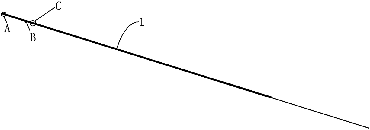
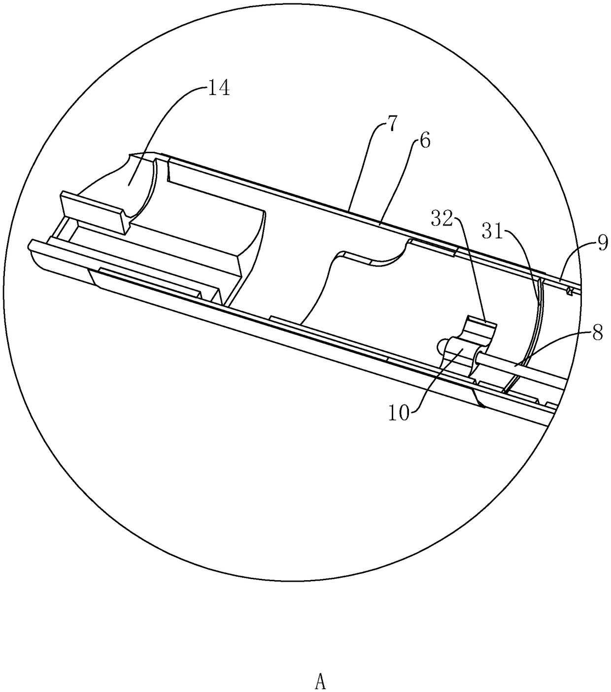
[0042] Example 1: Reference figure 1 , which is a ureteral catheter structure disclosed in the present invention, including a catheter body 1 , and the catheter body 1 includes a stepped braided tube 2 , a curved tube 3 and a plastic catheter head 14 .

[0043] refer to figure 2 and Figure 5 , wherein the stepped braided tube 2 can be made of nickel-titanium alloy, the stepped braided tube 2 and the curved tube 3 are spliced, the joint of the stepped braided tube 2 and the curved tube 3 is covered with the first stainless steel outer tube 4, and the first stainless steel outer tube 4 The outside is covered by the first PET heat-shrinkable film 5, and the first PET heat-shrinkable film 5 can undertake each component after being heat-shrinkable and wrapped.

[0044] The step braided pipe 2 is provided with a liner body 21, the liner body 21 makes the outer wall of the step braided pipe 2 form a stepped shoulder, and the liner body 21 can be used for sliding fit of the first st...

Embodiment 2

[0047] Embodiment 2: The difference with the embodiment is that, as Figure 7 and Figure 8 , the curved pipe 3 is divided into several snake joints 33 along its length direction, and each adjacent snake joint 33 is spliced ​​with each other but not connected. The snake joint 33 is provided with a guide convex circle 332 and a guide groove 333. The guide convex circle 332 and the guide groove 333 cooperate with each other to form relative rotation restrictions. The heat-shrinkable sleeve 9 recovers quickly from deformation. The serpentine joint 33 is formed with an inner convex ring 331 by stamping. The inner convex ring 331 can pass through the pulling wire 8 and serve as a guiding structure so that the pulling wire 8 passes through the stepped braided tube 2 at the other end.

[0048] like Figure 8 , the inner side of the step braided pipe 2 is provided with an inlay groove 22, and the inside of the inlay groove 22 is embedded with a stainless steel inner tube 12, and th...


PUM


Abstract

The invention discloses a ureteral catheter structure, and belongs to the technical field of inner tube structures in medical appliances, and solves the technical problem of unstable end deflection ofureter. A technical scheme is characterized in that that ureteral catheter structure comprises a catheter body, wherein the catheter body comprise a step braided tube, a bent tube and a plastic catheter head, wherein the step braided tube and the bent tube are connected with a first stainless steel outer tube, and the first stainless steel outer tube is covered with a first PET heat shrinkable film; A second stainless steel outer pipe is received between the bending pipe and the plastic pipe head, the second stainless steel outer pipe is covered with a second PET heat shrinkable film, and a traction wire is arranged in the pipe body, one end of the traction wire is fixed on the bending pipe, and the other end is passed out from the step braided pipe; Heat shrinkage sleeve is arranged outside the bent pipe; The technical effect is that the ureteral end can be bent independently to achieve a better detection effect.

Description

technical field [0001] The invention relates to the technical field of inner tube structures in medical appliances, in particular to a ureteral catheter structure. Background technique [0002] At present, ureteroscope is a kind of endoscope that uses special instruments to diagnose and treat diseases in the upper urinary tract of the urinary system. It does not need to make large incisions in the human body, which can significantly reduce the damage to the tissue, thereby speeding up the recovery of the body and shortening the course of treatment. It is an important development in endoscopic technology to improve the curative effect. Its clinical application has changed the traditional concept that the ureter and renal pelvis and calyx are difficult to perform visual inspection and that upper urinary tract diseases must be treated by open surgery. There are two types of ureteroscopes currently used: rigid ureteroscope and flexible ureteroscope. Rigid ureteroscope has the ad...

Claims


Application Information

Patent Timeline
Patent Type & Authority Applications(China)
IPC IPC(8): A61M25/00
CPCA61M25/0043A61M25/0045A61M25/005A61L29/10A61L29/02A61B1/0051A61B1/307C08L67/02A61L29/041A61L29/085A61M25/0053A61M2025/0059A61M2210/1078
Inventor 张一陈劲松
Owner STSIVITA MEDIKAL TECH KO LTD
Learn More