Full automatic V-groove cutting and edging machine

A fully automatic, edge folding machine technology, applied in the field of plate processing, can solve the problems of insufficient toughness of glue, complicated and cumbersome operation, colloid mixing, etc., and achieve the effects of strong aging resistance, good toughness, and promoting the bonding process

Pending Publication Date: 2019-01-18
顾银军
View PDF10 Cites 2 Cited by
  • Summary
  • Abstract
  • Description
  • Claims
  • Application Information

AI Technical Summary

Problems solved by technology

[0002] At present, the v-groove is cut on the wooden board, and then the board with the corresponding structural shape is obtained by folding the edge to meet different production needs. It is realized by changing the cutting tool, the operation is too complicated and cumbersome, and the machine usually needs to dispensing before the edge folding, and the equipment for dispensing generally drops the colloid directly into the v-groove without stirring the colloid. If it has not been used for a long time, you may find that it is impossible to dispense glue or it is difficult to dispense glue. Yellow glue is basically used when dispensing glue, and the toughness of the glue is not enough.

Method used


Image

  • Full automatic V-groove cutting and edging machine
  • Full automatic V-groove cutting and edging machine
  • Full automatic V-groove cutting and edging machine

Examples


Embodiment 1

[0052] The following is attached Figure 1-9 The present invention is described in further detail.

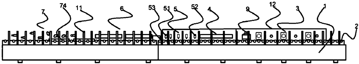
[0053] A fully automatic V-groove cutting and folding machine, such as figure 1 and figure 2 As shown, it includes the frame base 1 and the transmission device 2. The top of the frame base 1 is provided with a special placement groove, the transmission device 2 is fixed in the placement groove, and the frame base 1 is sequentially provided with three cutting machines along the length of the machine body Device 3, a preheating device 4, a dispensing device 5, two heating devices 6 and a set of hemming device 7, the preheating device 4 is fixedly connected with the frame base 1, and the preheating device 4 is set on the transmission device 2 Above, the dispensing device 5 is fixedly connected to the side of the frame base 1, the heating device 6 is fixedly connected to the frame base 1, the heating device 6 is also arranged above the transmission device 2, and the hemming devi...

Embodiment 2

[0064] The difference from Embodiment 1 is that the lower roller 28, the upper roller 34 and the fixed roller 91 are made of special materials.

[0065] Lower roller 28, upper roller 34 and fixed roller 91 are prepared by the following method:

[0066] Get the following raw materials for each component by weight: 30 parts of styrene-butadiene rubber, 20 parts of natural rubber, 8 parts of zinc oxide, 6 parts of calcium carbonate, 5 parts of titanium dioxide powder, 3 parts of natural paraffin, 3 parts of styrene, stearic acid 4 parts of zinc, 2 parts of tri-n-butyl citrate, 3 parts of p-phenylenediamine and 3 parts of diethylthiourea;

[0067] S1. Put the weighed styrene-butadiene rubber and natural rubber into the mixer and stir well, it is worth mixing the materials;

[0068] S2. Put the mixed material prepared in step S1 into the internal mixer for masticating, the temperature of the internal mixer is set to 120° C., and the internal mixing time is 15 minutes to obtain the...

Embodiment 3

[0074] The difference from Example 2 is that the formulation of the lower roller 28, the upper roller 34 and the fixed roller 91 is adjusted:

[0075] Get the following components by weight for subsequent use: 40 parts of styrene-butadiene rubber, 30 parts of natural rubber, 12 parts of zinc oxide, 10 parts of calcium carbonate, 8 parts of titanium dioxide powder, 6 parts of natural paraffin, 5 parts of styrene, stearic acid 7 parts of zinc, 4 parts of tri-n-butyl citrate, 5 parts of p-phenylenediamine and 5 parts of diethylthiourea;

[0076] S1. Put the weighed styrene-butadiene rubber and natural rubber into the mixer and stir well, it is worth mixing the materials;

[0077] S2. Put the mixed material prepared in step S1 into the internal mixer for masticating, the temperature of the internal mixer is set to 120° C., and the internal mixing time is 15 minutes to obtain the internal mixing material;

[0078] S3. Mix the banburying material prepared in step S2 and weighed zin...


PUM


Abstract

The invention discloses a full automatic V-groove cutting and edging machine. The full automatic V-groove cutting and edging machine comprises a machine body base, a transmission device, a cutting device, a lifting device, a pre-heating device, an adhesive dispensing device, an edging device, a dust sucking device and a heating device, wherein the transmission device is fixedly arranged on the topof the machine body base, the cutting device, the dust sucking device, the preheating device, the adhesive dispensing device, the heating device and the edging device are fixedly arranged on the machine body base in the length direction of the machine body and arranged above the transmission device, and the lifting device is arranged on the bottom of the cutting device and fixedly connected withthe machine body base. The cutting device is used for forming a V groove; the heating device and the preheating device can heat an adhesive for adhesive dispensing; the dust sucking device is used forsucking wood chips; the lifting device is used for adjusting the depth of the cut V shape; an adhesive stirring device is arranged on the adhesive dispensing device, and the adhesive is stirred so that adhesive dispersing can be facilitated; a white adhesive gun and a yellow adhesive gun are arranged on the adhesive dispersing device so that the toughness of the adhesive can be enhanced, and a running roller prepared by using the machine is resistant to ageing, tough and long in service life.

Description

technical field [0001] The invention relates to the technical field of plate processing, more specifically, it relates to a fully automatic V-groove cutting and folding machine. Background technique [0002] At present, the v-groove is cut on the wooden board, and then the board with the corresponding structural shape is obtained by folding the edge to meet different production needs. It is realized by changing the cutting tool, the operation is too complicated and cumbersome, and the machine usually needs to dispensing before the edge folding, and the equipment for dispensing generally drops the colloid directly into the v-groove without stirring the colloid. If it has not been used for a long time, you may find that it is impossible to dispense glue or it is difficult to dispense glue. Yellow glue is basically used when dispensing glue, and the glue is not tough enough. Contents of the invention [0003] In view of the deficiencies in the prior art, the purpose of the p...

Claims


Application Information

Patent Timeline
Patent Type & Authority Applications(China)
IPC IPC(8): B27F5/02B27M1/00B27G3/00B27G11/00C08L9/06C08L7/00C08L91/06C08K13/02C08K3/22C08K3/26C08K5/098
CPCC08L9/06B27F5/02B27G3/00B27G11/00B27M1/00C08L2205/03C08K2003/265C08K2003/2241C08L7/00C08L91/06C08K13/02C08K3/22C08K3/26C08K5/098
Inventor 顾银军
Owner 顾银军
Why Eureka
Try Eureka