Arrow anchor rod of multi-section clamping grouting anchoring and using method thereof

A multi-stage grouting technology, which is applied in the installation of bolts, earthwork drilling, mining equipment, etc., can solve the problems of uneven deformation of surrounding rock mass, reduction of shear force, failure, etc.

Active Publication Date: 2019-01-18
CENT SOUTH UNIV
View PDF11 Cites 14 Cited by
  • Summary
  • Abstract
  • Description
  • Claims
  • Application Information

AI Technical Summary

Problems solved by technology

However, for the common round steel bonded solid anchor rod widely used at present, it is divided into end anchorage or full-length anchorage, as a main supporting structure, but its anchoring agent is cement mortar and resin coil, and the anchorage in the hole wall The fullness is difficult to control, and the anchoring effect is also difficult to guarantee. In the reinforcement of rock and soil in complex environments, the rod body is often cut or pulled out to form a cavity in the surrounding rock and fail.
As a hollow grouting bolt suitable for unfavorable rock and soil layers, although the gap between the rod body and the hole wall is filled with grouting, and a protective anchoring layer with a uniform thickness is achieved, the cross-sectional size weakens its tensile strength. Solid anchor high resistance breaking pullout force
[0004] Furthermore, in order to enhance the comprehensive performance of traditional bolts and improve the stability of rock and soil under complex geological conditions, in the past inventions and technologies, most of the designed bolt support devices have optimized structures at the ends to enhance the anchoring force, or The anchoring strength of the designed segmental anchoring device is often insufficient, and its stability needs to be verified on site. Therefore, it has a single function or limited adaptability conditions, and it is difficult to adapt to geotechnical engineering with high ground stress or strong disturbance and strict deformation control.
For example, the patent CN104929670B discloses a wing-type anchor rod, in which an expandable clamping wing is provided on the anchoring section for anchoring at the end. The anchoring force of this anchor rod is mainly provided by the end wing device. The ability to resist bending moments is limited, and it is difficult to withstand complex geological environments
Patent CN107939427A discloses an energy-absorbing-seismic bolt that can greatly absorb the deformation energy of the surrounding rock and quickly yield pressure at the same time. It has many advantages such as high strength, stable support, elastic reset, and high damping. The r

Method used


Image

  • Arrow anchor rod of multi-section clamping grouting anchoring and using method thereof
  • Arrow anchor rod of multi-section clamping grouting anchoring and using method thereof
  • Arrow anchor rod of multi-section clamping grouting anchoring and using method thereof

Examples


Embodiment 1

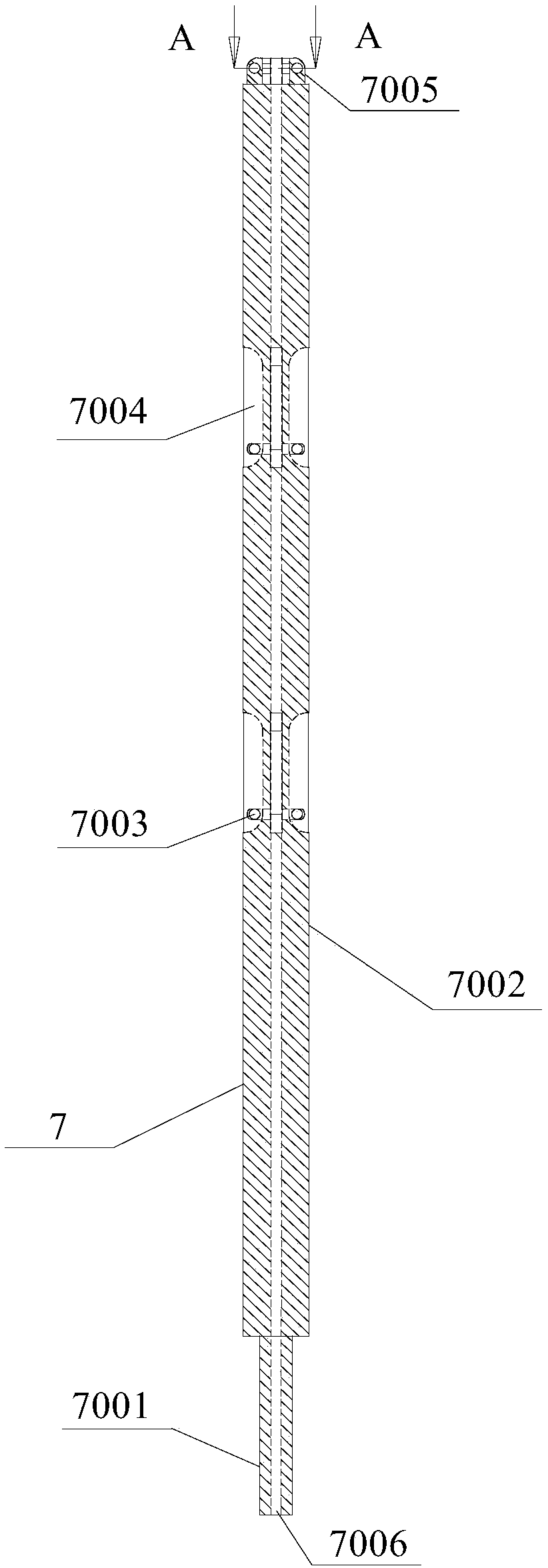
[0046] Such as figure 1 As shown, the present embodiment provides a multi-stage clamping and grouting anchor bolt, including a sleeve 5, a grouting rod device and a sealing device, the grouting rod device is arranged in the sleeve 5, and the grouting rod body The device includes a grouting rod body 7 and multiple groups of anchor heads 6. Each group of anchor heads 6 forms a clamping anchor structure and is hinged on the outer wall of the grouting rod body 7 with screws 8. The sleeve 5 is provided with anchor heads 6 one-to-one. And it is suitable for the slot hole through which the anchor head 6 passes. The solid sealing device includes a double-ended stud 2, a nut 3 and a tray 4. One end of the double-ended stud 2 is fastened between the cylinder body 5 and the grouting rod body 7 to form a tight The size fits, and the screw thread at the other end provides nut 3 to tighten and fix pallet 4.

[0047] Such as figure 2 As shown, the sleeve 5 includes an arrow structure 5003...

Embodiment 2

[0053] This embodiment provides a method for using a multi-stage clamping and grouting anchor bolt, including the following steps:

[0054] S1. Install the anchor head 6 on the grouting rod body 7, install the anchor head 6 on the base hole 7003 with the screw 8, and fix the front and rear ends of the screw 8 by soldering, and complete the assembly of all the anchor heads 6 in turn;

[0055] S2. Push one end of the anchor end of the grouting rod body 7 from the open end of the cylinder 5004. When the anchor head 6 reaches the slot 5002, it will pop out and get stuck. At this time, press it in by hand and continue to push it until it is anchored. The anchor head 6 on the end reaches the slotted hole 5002 at the tail end of the cylinder body 5004 and pops up;

[0056] S3, the device formed in the step S2 is packed into the drilled hole of the rock wall 9, and then the sleeve 5 is hammered by means of a tool (hammer or jack) so that the arrowhead structure 5003 is drilled into th...


PUM


Abstract

The invention relates to the field of slope reinforcement and surrounding rock support control of underground engineering, disclosing an arrow anchor rod of multi-section clamping grouting anchoring,which comprises a sleeve (5), a grouting rod body device and a sealing device, wherein the grouting rod body device is arranged in the sleeve (5); the grouting rod body device comprises a grouting rodbody (7) and a plurality of groups of anchor heads (6); each group of anchor heads (6) forms a clamping anchoring structure and are connected to the outer wall of the grouting rod body (7) in hinge mode; the sleeve (5) is provided with a slotted hole (5002) which is in one-to-one correspondence with the anchor head (6) and suitable for the anchor head (6) to pass; the anchor head (6) is guided into the rock mass along the slotted hole (5002) by the external force of propelling grouting rod body device; a sealing structure is formed between the sleeve (5) and the grouting rod body device by utilizing a sealing device and is fixed on the rock wall (9). By adopting the technical innovation of the arrow anchor rod of multi-section clamping grouting anchoring, continuous high-resistance and high-strength working resistance can be provided timely and efficiently, so that the long-term stability of the engineering geotechnical mass maintenance under the environment of high stress or strong power disturbance can be truly achieved.

Description

technical field [0001] The invention relates to the fields of side slope reinforcement and surrounding rock support control in underground engineering, in particular to a multi-section clamping grouting anchoring arrow bolt. Background technique [0002] At present, in the process of urban rail transit construction, excavation of mountain or hydropower tunnels, deep resource mining, and even major slope treatment projects, unfavorable rock and soil layers with complex occurrence conditions are often encountered, with well-developed joints, strong structural composites, and structural stresses. The level is high, and the anchoring quality of traditional bolts will be severely tested when the mine construction method is used for maintenance and control. If it is subjected to strong dynamic disturbances such as blasting excavation, mining disturbances, and seismic waves in the later stage, it is difficult to control the overall anchoring system at this time. Failure due to poor...

Claims


Application Information

Patent Timeline
IPC IPC(8): E21D21/00E21D20/02
CPCE21D20/02E21D21/0026E21D21/0046E21D21/0053
Inventor 李地元杜少华李夕兵周子龙
Owner CENT SOUTH UNIV
Why Eureka
Try Eureka