A symmetrical power converter circuit topology and control method thereof

A technology of circuit topology and power converter, which is applied in the directions of high-efficiency power electronic conversion, regulation of electric variables, control/regulation system, etc. Oxygen magnetic permeability changes and other issues, to achieve the effect of reducing reactive power loss, reducing design and manufacturing difficulty and cost, and reducing conduction loss

Pending Publication Date: 2019-01-18
ARMY ENG UNIV OF PLA
View PDF3 Cites 20 Cited by
  • Summary
  • Abstract
  • Description
  • Claims
  • Application Information

AI Technical Summary

Problems solved by technology

At present, the resonant frequency of the existing resonance compensation network is determined by the inductance or capacitance, coil self-inductance or mutual inductance in the compensation network. When the relative position between the coils changes, the coil self-inductance, mutual inductance and coupling coefficient between the coils will change accordingly. In addition, under different working temperature environments, the magnetic permeability of the ferrite in the coil structure will also change, which will lead to changes in the electrical parameters of the coil
In addition, the inductance error and capacitance error caused by mass production cannot be avoided
Therefore, in actual work, the resonant frequency will change to a certain extent. If the switching frequency deviates too much from the resonant frequency, it will cause serious problems such as hard switching of the high-frequency inverter, excessive reactive power loss, and reduced power output capability. ; If the switching frequency changes with the resonant frequency, the system will occupy a large frequency bandwidth resource under different working conditions. On the one hand, the relevant domestic and international standards limit the operating frequency range. The frequency range will make the system electromagnetic compatibility design more complicated and increase the system cost

Method used


Image

  • A symmetrical power converter circuit topology and control method thereof
  • A symmetrical power converter circuit topology and control method thereof
  • A symmetrical power converter circuit topology and control method thereof

Examples


Embodiment 1

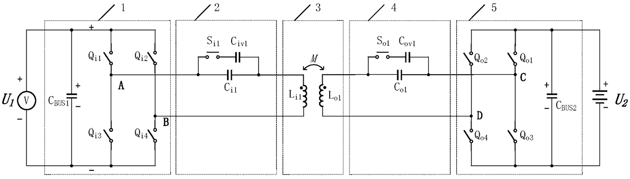
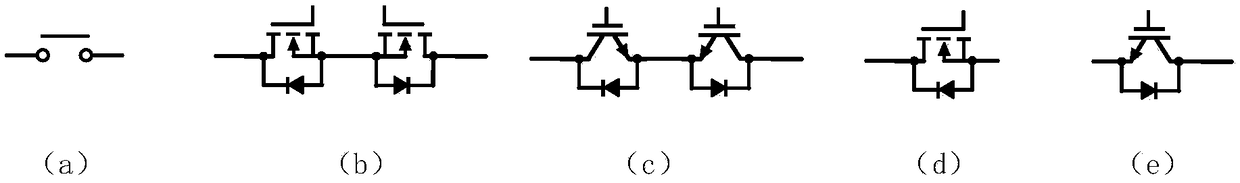
[0063] A circuit topology suitable for a two-way near-field power transmission system, in this embodiment, the first compensation switch S i1 and the second compensation switch S o1 The specific implementation mode is a single MOSFET, and the circuit topology of this embodiment is as follows Figure 9 shown.

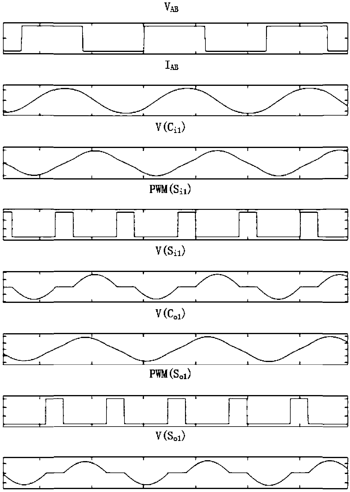
[0064] The first compensation switch S i1 and the second control switch S o1 The rising edge of the control PWM is related to the output voltage of the full-bridge inverter V AB rising edge aligned, the first compensation switch S i1 and the second control switch S o1 The control PWM signal is the same, the frequency of the control PWM is the same as the system operating frequency, and the simulation waveform when the high output voltage (400V) is obtained by adjusting the duty cycle of the control PWM is as follows Figure 10 As shown, the simulation waveform obtained by adjusting the duty cycle of the control PWM to obtain a low output voltage (260V) is as follow...

Embodiment 2

[0067] A circuit topology suitable for a two-way near-field power transmission system, in this embodiment, the first compensation switch S i1 and the second compensation switch S o1 The specific implementation mode is two MOSFETs connected in series, and the circuit topology of this embodiment is as follows Figure 12 shown.

[0068] The first compensation switch S i1 The positive pulse center of the control PWM and the capacitor C in the resonant network i1 The zero-crossing points of the voltages at both ends are aligned, the frequency of the control PWM is twice the operating frequency of the system, and the second compensation switch S o1 The positive pulse center of the control PWM and the capacitor C in the resonant network o1 The zero-crossing points of the voltage at both ends are aligned, and the frequency of the control PWM is twice the system operating frequency. By adjusting the duty cycle of the control PWM, the simulation waveform obtained when the high outpu...


PUM


Abstract

The invention discloses a circuit topology of a power converter suitable for bidirectional near-field electric energy transmission and a control method thereof. The circuit topology comprises a full-bridge inverter, a primary-side resonant dynamic compensation network, a primary-side coil, a secondary-side coil, a secondary-side resonant dynamic compensation network, a full-bridge synchronous rectification and a load. The invention adopts a structure that a coil is connected in series with an adjustable resonant capacitor, At different coil coupling coefficients, at different load size and dueto temperature, under the condition of system parameter change caused by manufacturing error of device, the resonant network can be dynamically compensated by adjusting the PWM duty cycle of the capacitor switching switch to produce a continuously variable equivalent series resonant capacitor, to achieve full-bridge inverter soft switching, minimize the reactive power in the system energy transfer, thereby maximizing the system power transfer efficiency, in the case of a constant operating frequency, effectively enhance the system output characteristics of the adjustment capability. In addition, because of the symmetry of the circuit structure, it can realize the bi-directional transmission of near-field electric energy, that is, the bi-directional energy flow between the power grid and the load, which improves the utilization rate of the system in the smart grid.

Description

technical field [0001] The invention relates to a power electronic topological circuit, in particular to a symmetrical power converter circuit topological structure and a control method thereof. Background technique [0002] The near-field power transmission is to convert the high-frequency circuit into an alternating electromagnetic field through the primary coil, and the high-frequency induced current generated in the secondary coil is converted into a DC output by a rectifier circuit. In recent years, this technology has been widely used in wireless charging products for smartphones. In addition, this technology also has broad application prospects in the fields of household robots, industrial robots, and electric vehicles. [0003] In order to improve the energy transmission distance and efficiency, a resonance compensation network can be added to the primary coil and the secondary coil respectively to form a magnetic resonance. At present, the resonant frequency of the...

Claims


Application Information

Patent Timeline
Patent Type & Authority Applications(China)
IPC IPC(8): H02M3/335H02J3/32
CPCH02J3/32H02M3/3353Y02B70/10
Inventor 李建科
Owner ARMY ENG UNIV OF PLA
Why Eureka
Try Eureka