
Movable in-situ analysis root box and using method thereof

An in-situ analysis and active technology, applied in the field of soil science, can solve the problems of high cost, poor applicability, and difficulty of in-situ and localized analysis of root morphological characteristics and the relationship between roots and soil. To achieve the effect of facilitating post-cleaning and maintenance, and realizing volume size adjustment

Pending Publication Date: 2019-01-22
SOUTH CHINA AGRI UNIV
View PDF5 Cites 2 Cited by
  • Summary
  • Abstract
  • Description
  • Claims
  • Application Information

AI Technical Summary

Problems solved by technology

Unfortunately, the cost of isotope tracer method, nuclear magnetic resonance method and microroot canal is too high; the existing various root boxes also have relatively large use defects, such as only satisfying the observation of root growth and only directional observation (less usefulness) ), can only observe some small plants (poor applicability), cannot be moved and disassembled (low recycling rate); these factors make it difficult to popularize and apply the existing root system in situ observation method in actual experimental research
In addition, due to the influence of soil opacity, compactness, mechanical properties, and layered properties, existing research methods are also difficult to analyze the morphological characteristics of the root system and the relationship between the root system and the soil, and cannot guarantee soil and plant root samples. Timeliness and accuracy of collection

Method used


Image

  • Movable in-situ analysis root box and using method thereof
  • Movable in-situ analysis root box and using method thereof
  • Movable in-situ analysis root box and using method thereof

Examples


Embodiment 1

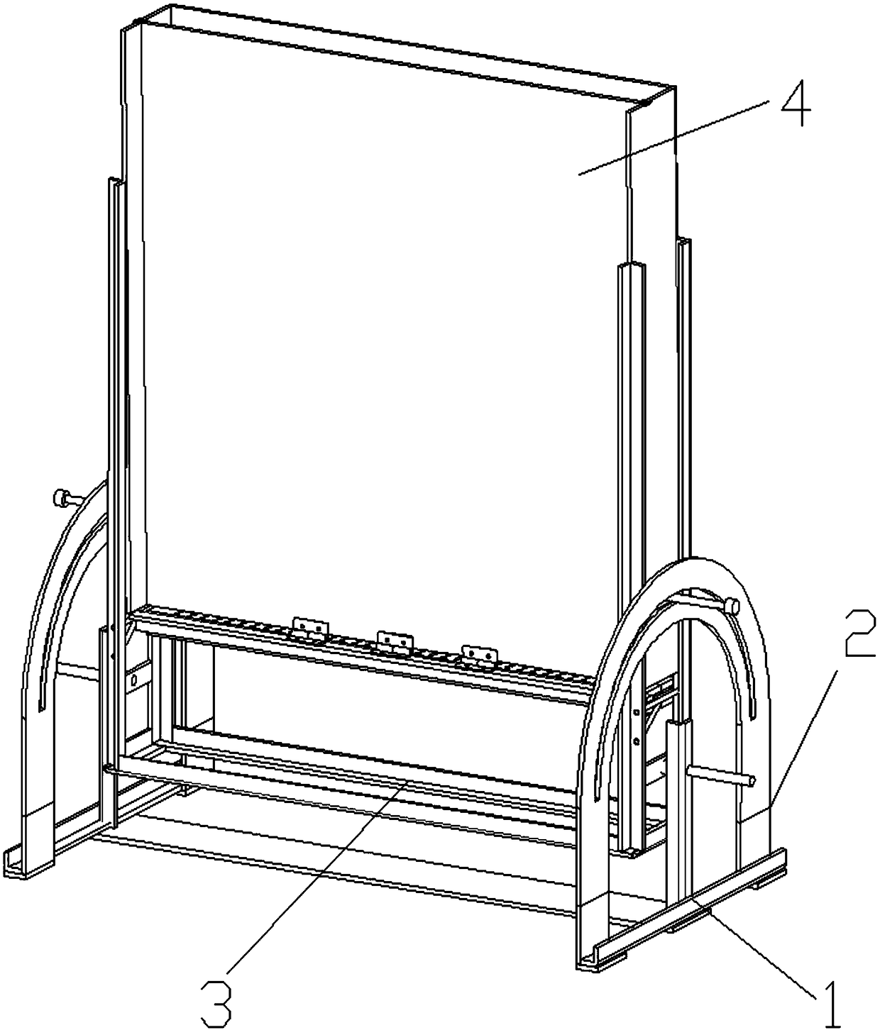
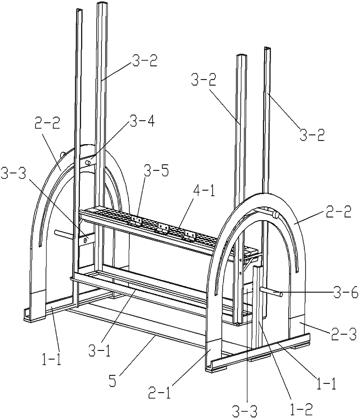
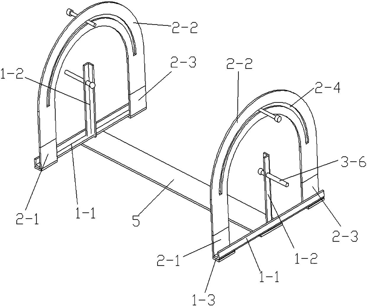
[0043] combine figure 1 As shown, a movable in-situ analysis root box includes a bracket, a box frame rotatably installed on the bracket, a plurality of solid side plates connected in sequence and fixed on the box frame, and a telescopic telescopic box mounted on the box frame. The living side panel installed on the box frame by block and translation. The box frame can rotate around the bracket, and the solid side panels are all set vertically, that is, the solid side panels are vertical, and each solid side panel is fixed on the box frame, and the sides of multiple solid side panels are sequentially connected together. The telescopic block can move up and down along the box frame, and the living side plate can translate back and forth on the box frame. The movable side panels that move horizontally along the inner walls of the fixed side panels are vertically arranged. In contact with each other, from a top view, the movable side panels and multiple fixed side panels form ...

Embodiment 2

[0064] Except the following technical features, all the other unmentioned technical features are the same as embodiment 1.

[0065] When using root boxes for in situ analysis, do the following:

[0066] Step 1: Set the volume of the cultivation room to 0.036m by adjusting the moving rod and the tripod 3 (600mm×600mm×100mm);

[0067] The second step: the cutting area is 600mm×100mm nylon cloth (the mesh is 0.025mm), and spread it on the bottom surface of the cultivation room (the upper surface of the telescopic block);

[0068] The third step: put the red soil that has been naturally air-dried and passed through a 2mm sieve into the cultivation room, water it thoroughly, and properly compact the red soil in the cultivation room;

[0069] The fourth step: Transplant the half-year-old yellow beam seedlings into the cultivation room and cover them with shading insulation film; by adjusting the bolts connected to the rotating parts connected to the second longitudinal rod of the ...

Embodiment 3

[0075] Except the following technical features, all the other unmentioned technical features are the same as embodiment 1.

[0076] When using root boxes for in situ analysis, do the following:

[0077] Step 1: Set the volume of the cultivation room to 0.0108m by adjusting the moving rod and the tripod 3 (600mm×300mm×60mm);

[0078] The second step: the cutting area is 600mm×60mm nylon cloth (the mesh is 0.025mm), and spread it on the bottom surface of the cultivation room (the upper surface of the telescopic block);

[0079] Step 3: mix the red soil and urban sewage sludge (both naturally air-dried and passed through a 2mm sieve) in a mass ratio of 1:1, put them into the cultivation room, water them thoroughly, and properly compact the cultivation room matrix;

[0080] Step 4: Transplant the 1-year-old seedlings of Scherichia hemanthus into the cultivation room, cover with shading and thermal insulation film; connect the rotating part connected with the second vertical rod ...


PUM


Abstract

The invention relates to a movable in-situ analysis root box. The box comprises a bracket, a box frame rotatably mounted on the bracket, a plurality of fixed side plates sequentially connected with and fixed to the box frame, a telescopic block mounted on the box frame in a lifting manner and a movable side plate mounted on the box frame in a translational manner; the fixed side plates are vertically disposed, the movable side plate horizontally moving along the inner walls of the fixed side plates are vertically disposed, the two sides of the movable side plate respectively contact with the inner walls of the fixed side plates, and the movable side plate and the plurality of fixed side plates enclose a closed area when looking down; the telescopic block vertically moving along the inner walls of the fixed side plates are horizontally disposed, one end of the telescopic block and the inner wall of one certain fixed side plate are in contact with each other, the other end of the telescopic block is mounted on the box frame in a lifting manner, and the two sides of the telescopic block are respectively in contact with the inner walls of the two fixed side plates. The invention also relates to a using method for the movable in-situ analysis root box. The root box can observe, analyze and sample different plants in situ, and belongs to the technical field of soil science.

Description

technical field [0001] The invention belongs to the technical field of soil science, and specifically relates to a movable in-situ analysis root box and a using method thereof. Background technique [0002] Plants mainly obtain nutrients and water from the soil through the root system, and the morphological characteristics of the root system and the relationship between the root system and the soil directly affect the growth of the plant. Therefore, in the related research of efficient utilization of plant nutrients, plant stress tolerance, and plant water and soil conservation efficiency, great attention has been paid to the study of the physiological and ecological characteristics of roots in soil and the relationship between roots and soil. [0003] However, the complexity and invisibility of plant roots in soil limit the above-mentioned related research to some extent. In order to promote related research, people have tried a variety of methods to carry out in situ obse...

Claims


Application Information

Patent Timeline
IPC IPC(8): A01G9/02A01G7/06G01N21/84
CPCA01G7/06A01G9/02G01N21/84G01N2021/8466Y02P60/21
Inventor 吴道铭张书源古敏邹璇董晓全
Owner SOUTH CHINA AGRI UNIV
Learn More