Pipeline laying structure applied to high-speed geotechnological centrifugal machine

A geotechnical centrifuge and centrifuge technology, applied in the field of centrifuges, can solve the problems of destroying the aerodynamic shape of the rotating arm, increasing the stress value at the opening position, and breaking the pipeline, achieving low overall structural strength, simple installation and disassembly, and guaranteed use. safe effect

Pending Publication Date: 2019-01-25
GENERAL ENG RES INST CHINA ACAD OF ENG PHYSICS
View PDF7 Cites 0 Cited by
  • Summary
  • Abstract
  • Description
  • Claims
  • Application Information

AI Technical Summary

Problems solved by technology

However, the arrangement of existing pipes and cables makes them protrude from the upper surface of the rotating arm, which destroys the good aerodynamic shape of the rotating arm and increases the wind resistance of the centrifuge operation
[0009] 2. Weak protection ability
Therefore, it often happens that the internal battery core of the cable is broken by the crimping clamp during installation.
[0011] Secondly, because the cable is wrapped with elastic materials such as rubber skin, the cable between the crimping clamps will shake back and forth under the action of centrifugal force and wind resistance, so that the internal battery core of the cable will break after a period of use (for electric especially for signal cables with thin cores)
[0012] In addition, when the acceleration of the centrifuge reaches 1000g, the traditional pipeline installation structure will not be able to provide enough friction to balance the centrifugal force on the pipeline, otherwise it will cause too much compression force to cause cable breakage and pipeline rupture
[0013] 3. Affect the structural strength of the boom
[0015] However, for high-speed geotechnical centrifuges, under the centrifugal acceleration of 1000g, the force on the arm deteriorates sharply, and the maximum internal stress is close to the allowable stress of the material
Processing the screw holes for installing pipelines on the rotating arm will cause the stress value at the opening position to increase significantly and exceed the allowable stress of the material, making the rotating arm very prone to structural damage at the screw hole under high centrifugal field, seriously affecting the high-speed Safe Operation of Geotechnical Centrifuge

Method used


Image

  • Pipeline laying structure applied to high-speed geotechnological centrifugal machine
  • Pipeline laying structure applied to high-speed geotechnological centrifugal machine
  • Pipeline laying structure applied to high-speed geotechnological centrifugal machine

Examples


Embodiment 1

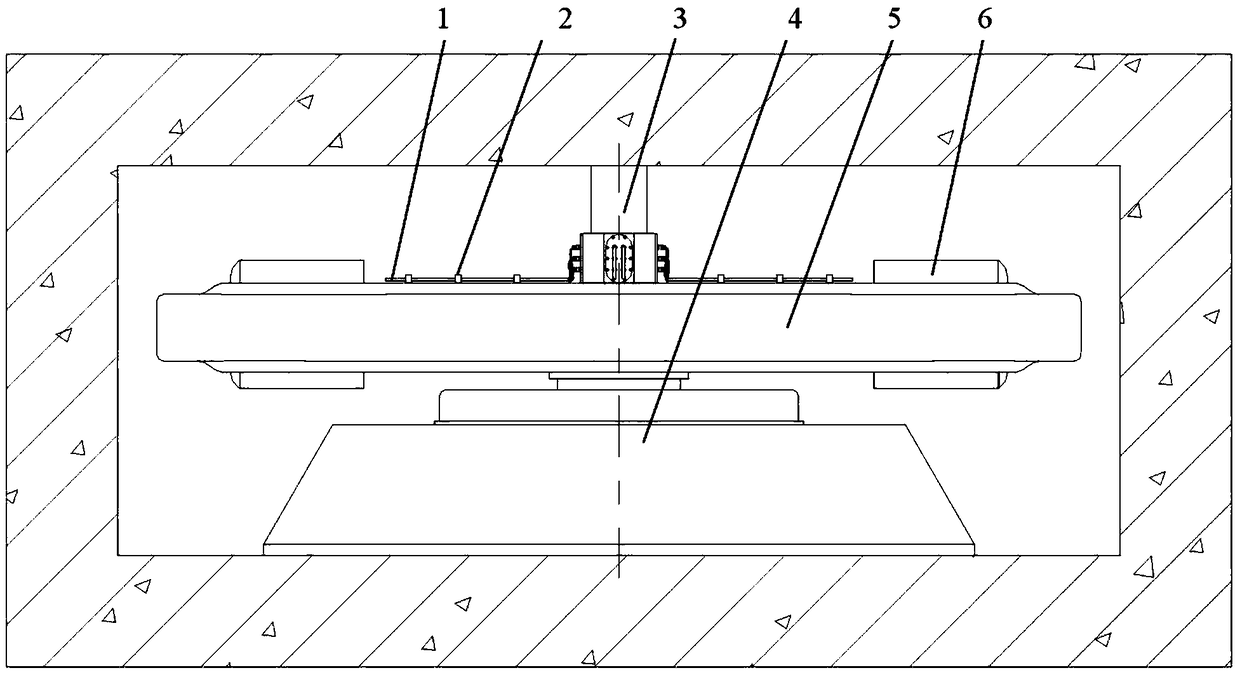
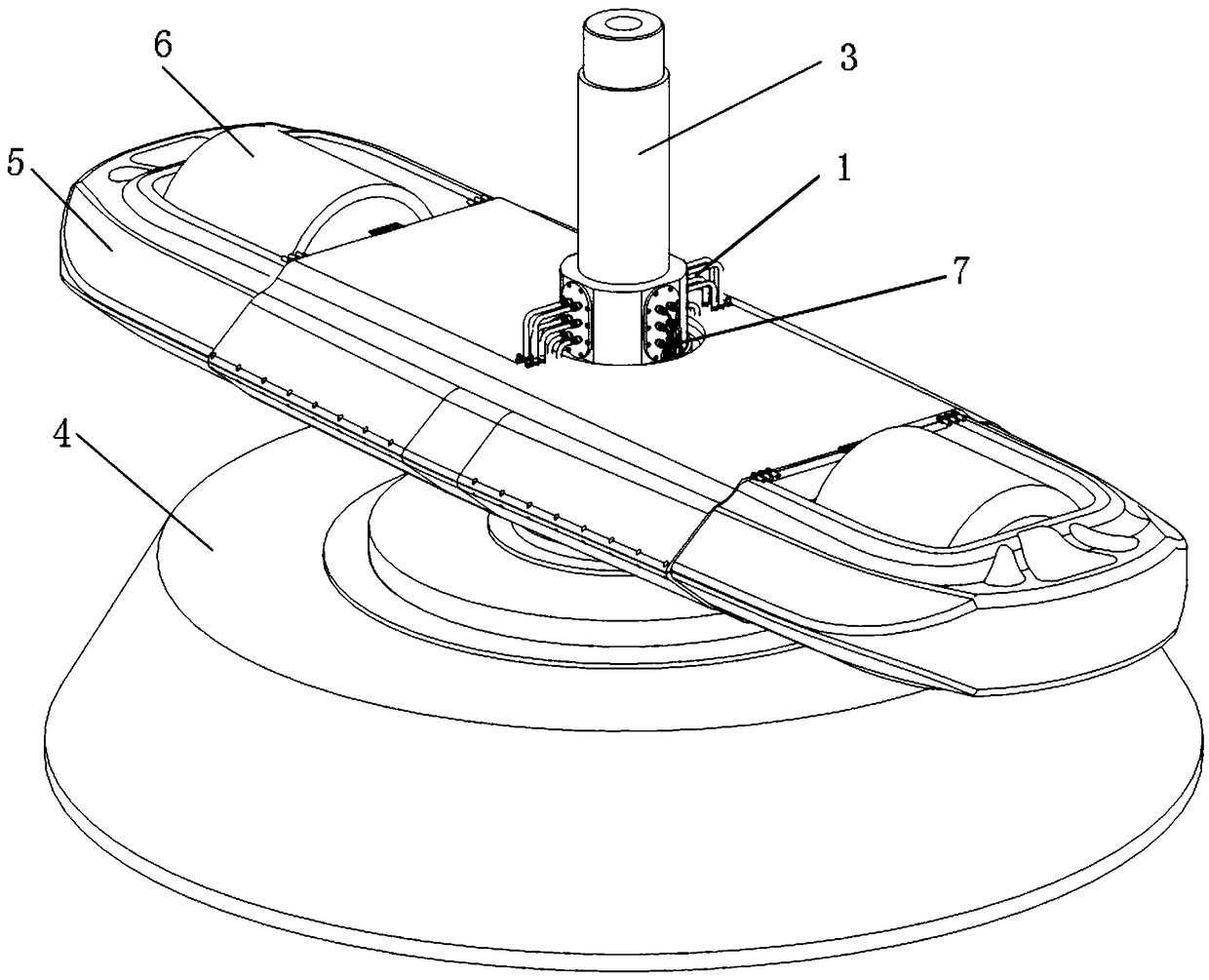
[0051] Example 1, such as figure 2 and image 3 as shown,

[0052] A pipeline laying structure applied to a high-speed geotechnical centrifuge, which is used to supply water, air, and power from the rotating shaft 3 of the centrifuge to the hanging basket 6 of the centrifuge. The pipeline laying structure is tightly fitted on the rotating arm 5 of the centrifuge , the pipeline laying structure is integrally solidified with a pipeline 1 and a cable 7, and the two ends of the pipeline 1 are respectively connected with a pipe joint 11, and the two ends of the cable 7 are respectively connected with a cable plug 13; the pipeline laying structure passes through two pipe joints 11 They are respectively connected to the water supply and air supply interfaces on the rotating shaft 3 and the water supply and air supply interfaces on the hanging basket 6, and the pipeline laying structure is respectively connected to the power supply interface on the rotating shaft 3 and the power sup...

Embodiment 2

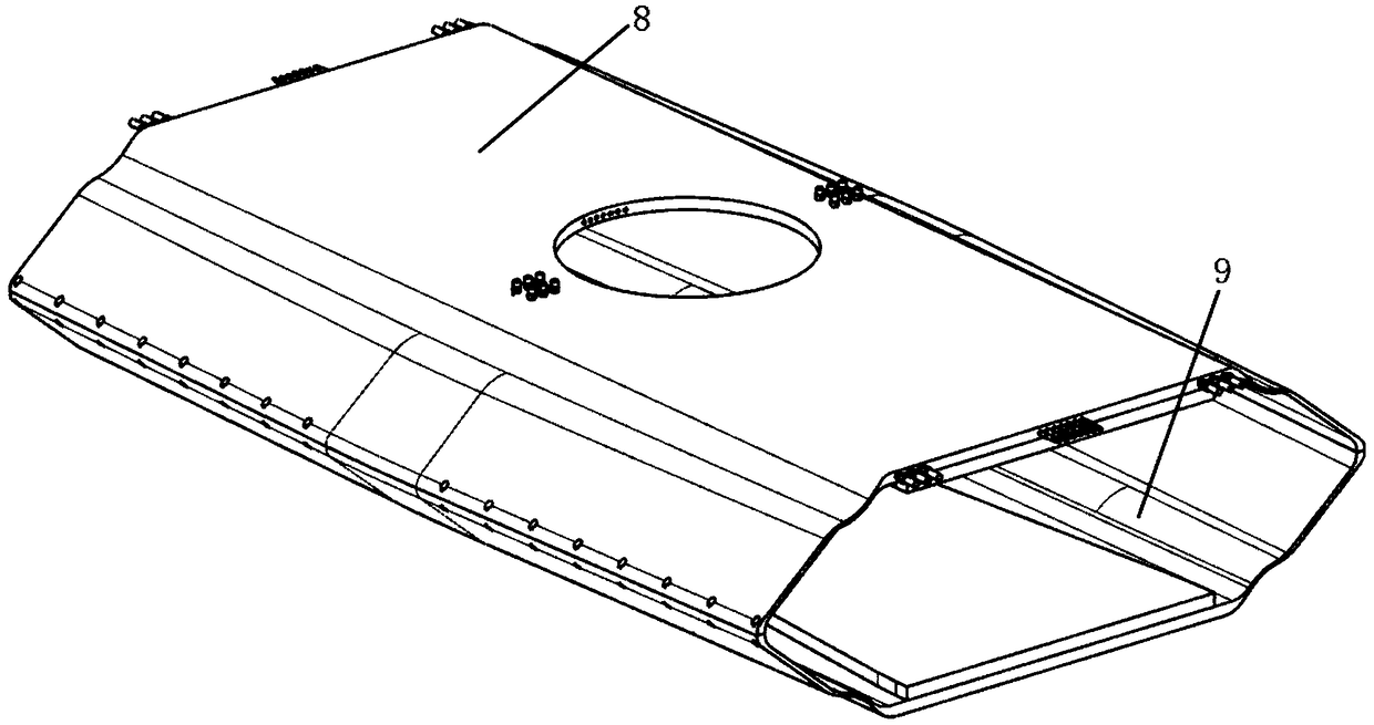
[0054] Example 2, such as image 3 and Figure 4 as shown,

[0055] The difference between this embodiment and embodiment 1 is:

[0056] The pipeline laying structure includes:

[0057] The upper bracket 8; the upper bracket 8 includes a casing 12, the pipeline 1 and the cable 7 are integrally formed inside the casing 12, and the lower surface of the upper bracket 8 casing 12 is attached to the upper part of the rotating arm 5;

[0058] The lower bracket 9; the lower bracket 9 includes a shell 12, the upper surface of the lower bracket 9 shell 12 is attached to the lower part of the rotating arm 5, and the middle part of the upper bracket 8 shell 12 and the lower bracket 9 shell 12 is provided with a hole for the shaft 3 to pass through Screw mounting holes are reserved on both sides of the upper bracket 8 and the lower bracket 9, and the two sides of the upper bracket 8 shell 12 are respectively connected with the two sides of the lower bracket 9 shell 12 through a plurali...

Embodiment 3

[0061] Example 3, such as image 3 as shown,

[0062] The difference between this embodiment and embodiment 2 is:

[0063] The surfaces of the upper bracket 8 and the lower bracket 9 are smooth and continuous.

[0064] The shells 12 are molded and solidified in a special mold, so the outer surfaces of the upper bracket 8 and the lower bracket 9 are smooth and continuous, and the aerodynamic resistance is small, thereby reducing the wind resistance of the geotechnical centrifuge.


PUM


Abstract

The invention discloses a pipeline laying structure applied to a high-speed geotechnological centrifugal machine. According to the structure, pipelines and cables are integrally cured and molded in the pipeline laying structure to reduce protruding matters on the outer surface of a rotary arm of the geotechnological centrifugal machine, so that the whole centrifugal machine has a better aerodynamic shape to help to reduce wind resistance, heat generated by friction and energy consumption; the rotary arm of the centrifugal machine is tightly sleeved with the pipeline laying structure, the direct pressing force of the pipelines, the cables and the rotary arm is replaced with a sleeve pressing force of the pipeline laying structure and the rotary arm, the pressing force is larger, the connection is more stable, and damage on the pipelines and the cables is not caused; the installation and dismantling of the pipeline laying structure is simple, a large number of screw holes do not need tobe reserved in the rotary arm of the geotechnological centrifugal machine, so that stress concentration on a local region on the rotary arm is not caused, and therefore the using safety of the rotaryarm can be effectively protected.

Description

technical field [0001] The invention belongs to the technical field of centrifuges, and in particular relates to a pipeline laying structure applied to high-speed geotechnical centrifuges. Background technique [0002] Geotechnical centrifuge is an experimental device used in geotechnical engineering and other fields. It can simulate the supergravity field by using the stable centrifugal acceleration field formed by high-speed rotation. According to the similarity ratio principle of the model, researchers can conduct experimental research on real-world 100-meter-high dams and giant landslides on geotechnical centrifuges to evaluate their safety and grasp the mechanism of landslides. In addition, geotechnical centrifuges are also widely used in deep sea engineering, underground environmental pollutant assessment, earthquake resistance assessment of urban building structures, high-energy explosion research and other fields. The field provides strong support. [0003] High-sp...

Claims


Application Information

Patent Timeline
Patent Type & Authority Applications(China)
IPC IPC(8): B04B15/00
CPCB04B15/00
Inventor 陈良军冉光斌宋琼罗龙王黎光许元恒李心耀王鑫磊
Owner GENERAL ENG RES INST CHINA ACAD OF ENG PHYSICS
Why Eureka
Try Eureka