Zinc-halide battery using a deep eutectic solvent-based electrolyte
A technology of deep eutectic solvent and electrolyte, which is applied in the field of improving the performance of electrochemical battery cells, and can solve problems such as the unsuccessful commercialization of zinc chloride batteries
- Summary
- Abstract
- Description
- Claims
- Application Information
AI Technical Summary
Problems solved by technology
Method used
Image
Examples
example 1
[0204] Example 1: Deep eutectic solvent ZnCl 2 4H 2 Optimization of the ratio of O to TEABr ratio in non-aqueous electrolytes.
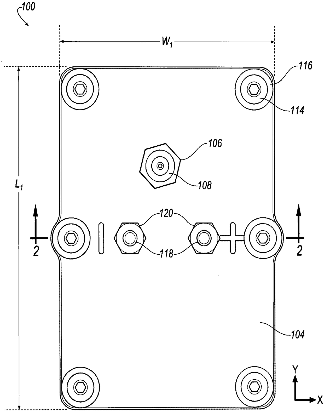
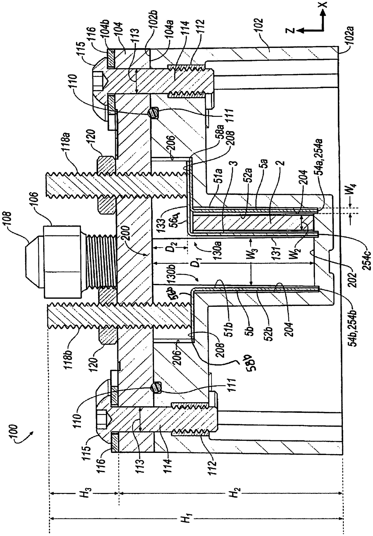
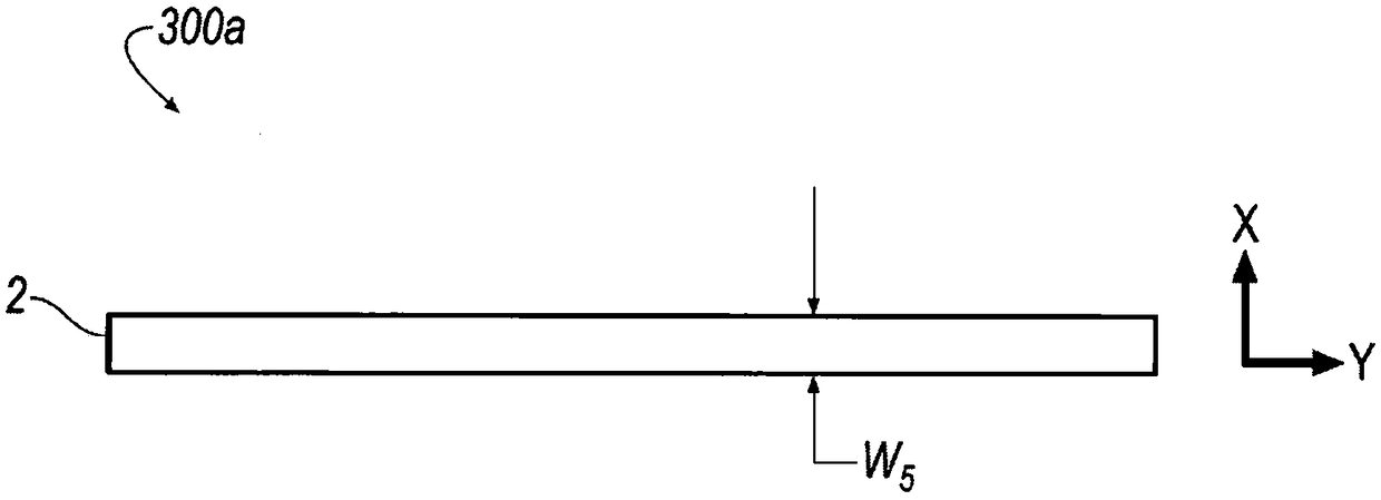
[0205] During the charge and discharge cycles of electrochemical cells, the use of ZnCl 2 4H 2 The electrochemical performance parameters were measured in non-aqueous electrolyte solution formed by the mixture of O and TEABr deep eutectic solvent. Using rechargeable zinc halide ambulatory electrochemical cells such as figure 1 , 2 , 3A and 3B, comparing different molar ratios of ZnCl 2 4H 2 Electrochemical performance parameters of non-aqueous electrolyte solutions of O and TEABr. Make ZnCl with a given molar ratio 2 4H 2 A non-aqueous electrolyte solution of O and TEABr is inserted between the bipolar electrodes 130a, 130b in the receiving area of the battery cell 100 and the cover 104 is secured to the housing 102 to seal the battery cell 100 . When using a given molar ratio of ZnCl 2 4H 2 After measuring the electrochemical performa...
example 2
[0206] Example 2: Effect of hydrogen bond donors on electrolyte performance.
[0207] Comparison of different equimolar amounts of hydrogen bond donors (added to ZnCl 2 4H 2 Electrochemical performance parameters of non-aqueous electrolytes in O with the amount of TEABr used in the deep eutectic solvent mixture of TEABr). Comparison of electrochemical performance parameters shows that addition of hydrogen bond donors increases the activity of the halides in the system, increases the potential of the redox couple, increases the peak power reduction and increases the slope at low overpotentials to indicate a decrease in charge transfer resistance . Figure 5 Tafel slopes performed on a glassy carbon electrode with a deep eutectic solvent obtained with Figure 4 Formation of the same ingredients as described in . In this case, the hydrogen bond donors (acetic acid, CH 3 COOH) was added in an equimolar amount to the amount of TEABr used. Adding a hydrogen bond donor increase...
example 3
[0208] Example 3: Aqueous vs. non-aqueous electrolytes.
[0209] used in pairs made of ZnCl 2 4H 2 A non-aqueous electrolyte solution formed from a mixture of O and TEABr deep eutectic solvent and aqueous zinc bromide (ZnBr) with TEABr complexing agent 2 ) electrochemical performance parameters are measured and compared during charge and discharge cycles of the electrochemical cell in the electrolyte solution. Make aqueous ZnBr with TEABr complexing agent 2 The electrolyte solution is inserted between the bipolar electrodes 130 a , 130 b within the receiving area of the battery cell 100 and secures the cover 104 to the housing 102 to seal the battery cell 100 . In the case of using aqueous ZnBr with TEABr complexing agent 2 Electrochemical performance parameters, such as electrolytic potential, are measured during cyclic voltammetry of a battery cell in an electrolyte solution. Thereafter, the cover 104 is removed from the housing 102 by loosening the bolt 114 to use 2...
PUM
 Abstract
Description
Claims
Application Information
 - R&D
- Intellectual Property
- Life Sciences
- Materials
- Tech Scout
- Unparalleled Data Quality
- Higher Quality Content
- 60% Fewer Hallucinations
Browse by: Latest US Patents, China's latest patents, Technical Efficacy Thesaurus, Application Domain, Technology Topic, Popular Technical Reports.
© 2025 PatSnap. All rights reserved.Legal|Privacy policy|Modern Slavery Act Transparency Statement|Sitemap|About US| Contact US: help@patsnap.com


