Reversible electro-optic device employing aprotic molten salts and method

Inactive Publication Date: 2005-03-01
LOS ALAMOS NATIONAL SECURITY
View PDF16 Cites 35 Cited by
  • Summary
  • Abstract
  • Description
  • Claims
  • Application Information

AI Technical Summary

Benefits of technology

wherein R22, R23, R24 and R25 are individually selected from a group consisting of hydrogen, alkyl containing 5 to 20 carbon atoms, alkenyl containing 2 to 20 carbon atoms, alkynyl containing 2 to 20 carbon atoms, and aryl containing 5 to 20 carbon atoms which are unsubstituted or optionally substituted with one or more ester, ether, aryl, amine, thioester, alkyl, alkoxy, alkene, alkyne, cyano, fluoride, chloride, bromide, iodide, organometallocene functional groups, or combinations thereof; radical cations of hydrazone compounds selected from the group consisting of acetone 2,2-dimethylhydrazone, 2-pentanone 2ethyl-2-methylhydrazone, 2-ethylbutanal 1-ethyl-1-propylhydrazone, 2-ethyl-2-nonanone 2-hexyl-2-propylhydrazone, (E)-3-nonen-2-one 2-butyl-2-propylhydrazone, 2-hexanone 2-[(E)-2-butenyl]-2-[(Z)-2-butenyl]-hydrazone, 4-pentyn-2-one 2,2-dipropylhydrazone, 1-penten-3-one 3,3-dimethylhydrazone, 2-hexanone 2,2-diphenylhydrazone, 3-heptanone 3-methyl-3-phenylhydrazone, 1-ethoxy-2-butanone 2-methyl-2-phenylhydrazone, 1-phenylacetone 2-(3-methoxyphenyl)-2-phenylhydrazone, 2-phenacetaldehyde 1-methyl-1-phenylhydrazone, methyl 3-[(Z)-2-methyl-2-ph

Problems solved by technology

Sunlight transmitted through windows in buildings and transportation vehicles can generate heat (via the greenhouse effect) that creates an uncomfortable environment and increases air conditioning requirements and costs.
These approaches are only partially effective because the window itself is heated and because these devices, such as electrochromic devices, are relatively expensive and exhibit limited durability and cycle life.
Another limitation of electrochromic devices is that many employ organic dyes that have limited stability to ultraviolet light; absorb light rather than reflect it and therefore only partially reduce solar thermal burdens; and do not offer privacy or complete opacity.
Certain liquid crystal-based window systems switch between transmissive and opaque/scattering states, but these systems require substantial voltages to maintain the transparent state.
Bright light from headlamps on following vehicles reflected in automobile rear and side view mirrors is annoying to drivers and creates a safety hazard by impairing driver vision.
Such devices do not provide close control over the amount of reflected light, and are expensive to fabricate since a very constant inter-electrode spacing is required to provide uniform dimming.
In prior art attempts to exploit reversible electrodeposition of a metal for light modulation, the deposits obtained on transparent substrates presented a rough and black, gray, or sometimes colored appearance (typical

Method used


Image

  • Reversible electro-optic device employing aprotic molten salts and method
  • Reversible electro-optic device employing aprotic molten salts and method
  • Reversible electro-optic device employing aprotic molten salts and method

Examples


example 1

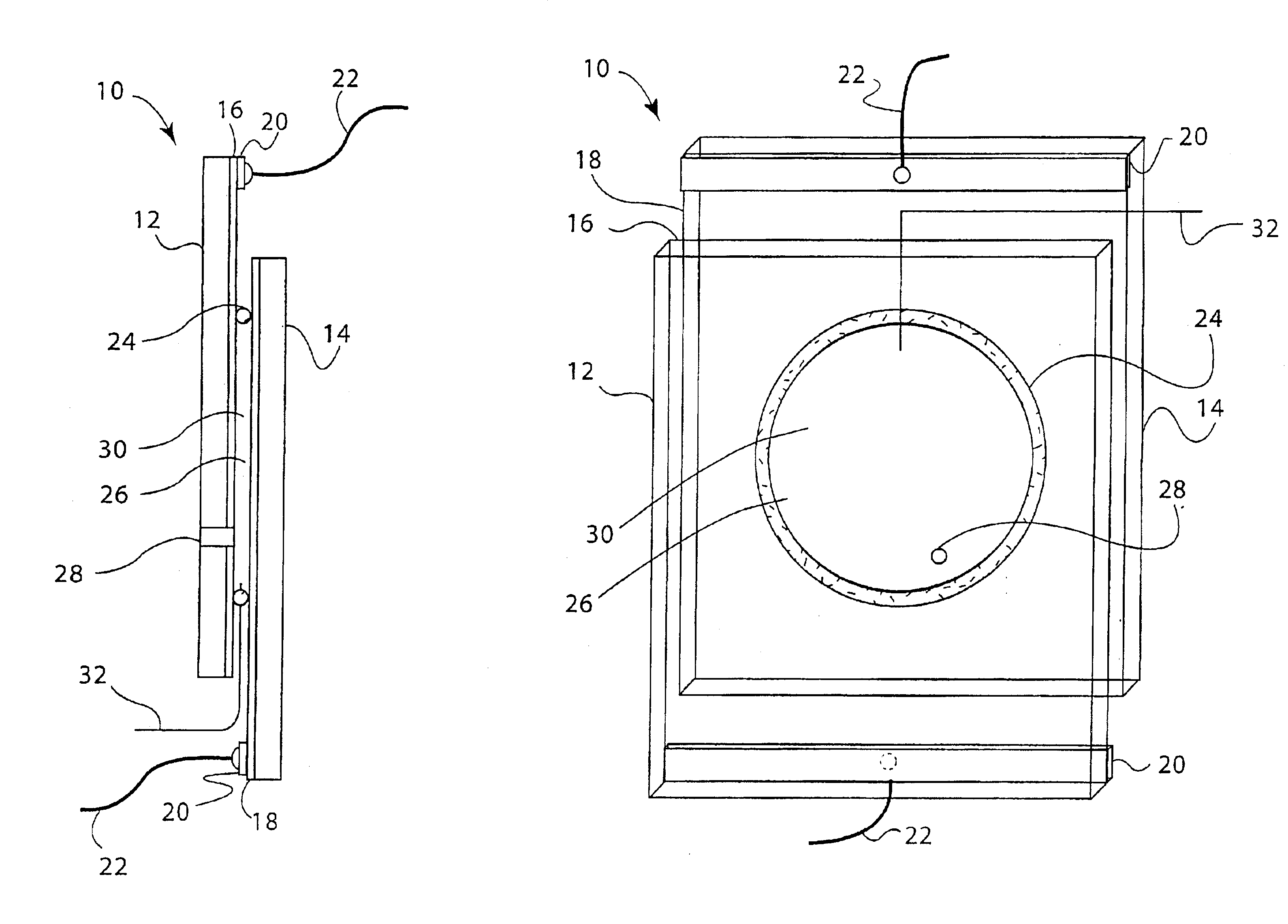
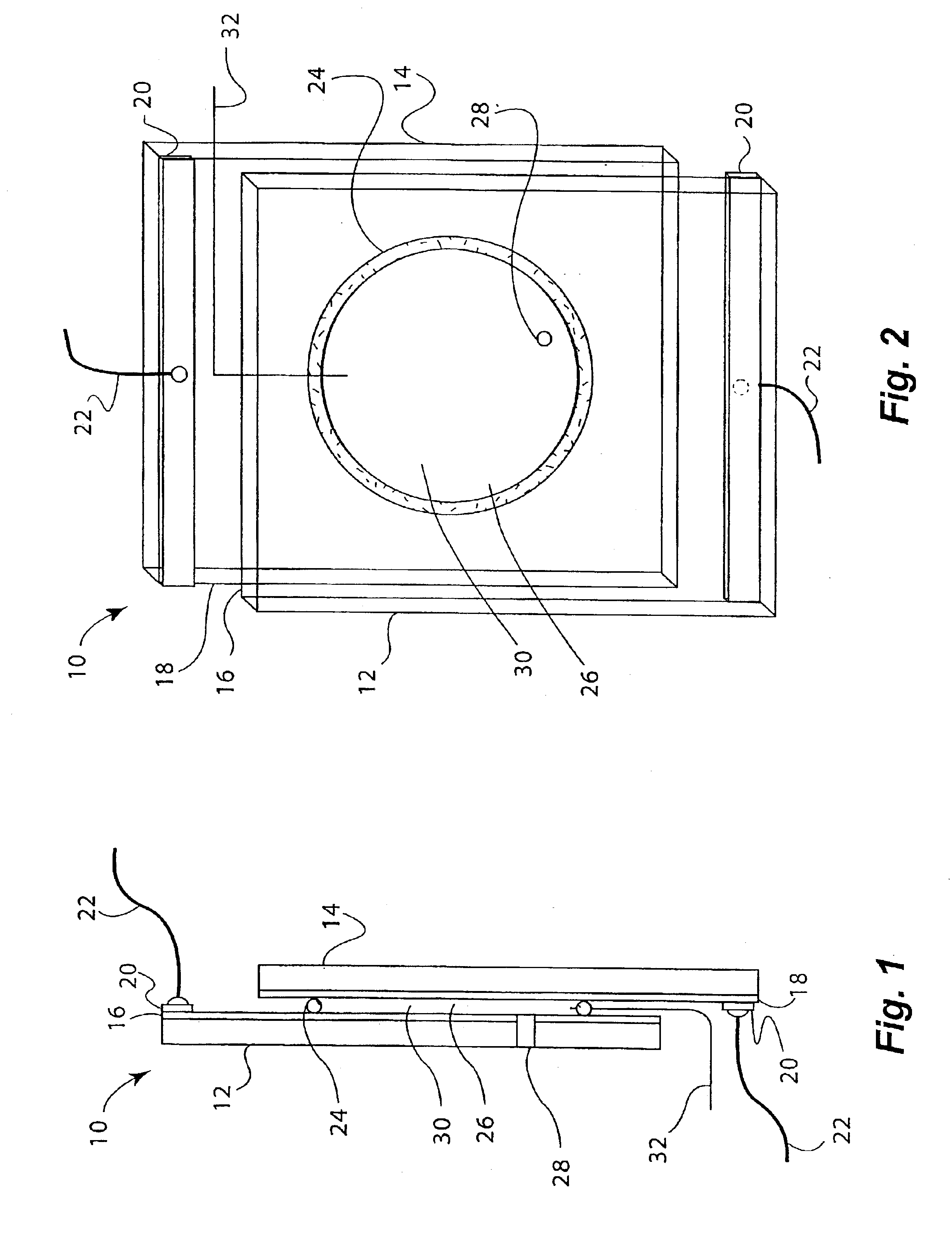
An embodiment of a reversible mirror of the invention was fabricated as follows: two electrodes were prepared using 6×8 cm single-side planar ITO coated glass plates having a sheet resistivity of 7Ω / square. Each plate was provided with a bus bar by attaching a copper electrical contact approximately 1 cm wide along the entire edge of the 6 cm end of each plate. The electrodes were then washed with water, methanol and acetone, and dried in a stream of warm air to remove any dust or grease.

An o-ring (2 cm internal diameter (ID) vycor rubber donut-shaped o-ring, 0.3 cm thick) was used as a gasket to seal one electrode to the other. A silver wire (5 cm long, 0.25 mm diameter, 99.9% metal purity) was inserted through the o-ring by first piercing a hollow needle through the o-ring, placing one end of the silver wire through the hollow needle, and then withdrawing the hollow needle from the o-ring. Approximately 0.4 mm of the silver wire protruded through the o-ring. The o-ring was then pl...

example 2

A second working embodiment of a reversible mirror of the invention was fabricated using the general procedure provided in EXAMPLE 1 but with a solution of 3-butyl-1-methylimadazolium bis(trifluoromethylsulfonyl)imide (also containing less than 1 ppm water) and 0.792 mol / L of iron (II) is(trifluoromethylsulfonyl)imide. An iron mirror was deposited at a potential of −1.2 Volts versus the silver reference electrode. Twenty minutes after the potential was removed, the iron mirror deplated spontaneously. Overall, this reversible mirror device exhibited good optical reflectance in the reflective state and good transparency in the non-mirrored state, and was switched repetitively between these two states without degradation of performance.

example 3

A third working embodiment of a reversible mirror of the invention was fabricated using the general procedure provided in EXAMPLE 1 but with a solution of solution of 3-butyl-1-methylimadazolium bis(trifluoromethylsulfonyl)imide containing less than 1 ppm water and 0.073 mol / L ferrocene was used. By contrast to EXAMPLE 2, the iron is initially present as ferrocene. An iron mirror was initially deposited at a potential of −1.5 Volts versus the silver reference electrode. This iron mirror was deplated at a potential of +0.4 Volts versus the silver reference electrode and redeposited at a potential of −1.2 Volts versus the silver reference electrode. Overall, this reversible mirror device exhibited good optical reflectance in the reflective state and good transparency in the non-mirrored state, and was switched repetitively between these two states without degradation of performance.


PUM


Abstract

A single-compartment reversible mirror device having a solution of aprotic molten salt, at least one soluble metal-containing species comprising metal capable of being electrodeposited, and at least one anodic compound capable of being oxidized was prepared. The aprotic molten salt is liquid at room temperature and includes lithium and/or quaternary ammonium cations, and anions selected from trifluoromethylsulfonate (CF3SO3), bis(trifluoromethylsulfonyl)imide ((CF3SO2)2N), bis(perfluoroethylsulfonyl)imide ((CF3CF2SO2)2N) and tris(trifluoromethylsulfonyl)methide ((CF3SO2)3C). A method for preparing substantially pure molten salts is also described.

Description

FIELD OF THE INVENTIONThe present invention relates generally to reversible mirrors and more particularly to a reversible mirror employing aprotic molten salts and to molten salt electrolyte solutions.BACKGROUND OF THE INVENTIONSunlight transmitted through windows in buildings and transportation vehicles can generate heat (via the greenhouse effect) that creates an uncomfortable environment and increases air conditioning requirements and costs. Current approaches to providing “smart windows” with adjustable transmission for use in various sunlight conditions involve the use of light absorbing materials. These approaches are only partially effective because the window itself is heated and because these devices, such as electrochromic devices, are relatively expensive and exhibit limited durability and cycle life. Another limitation of electrochromic devices is that many employ organic dyes that have limited stability to ultraviolet light; absorb light rather than reflect it and there...

Claims


Application Information

Patent Timeline
IPC IPC(8): G02F1/01G02F1/15G02F1/1506
CPCG02F1/1506C07D295/023
Inventor WARNER, BENJAMIN P.MCCLESKEY, T. MARKBURRELL, ANTHONY K.HALL, SIMON B.
Owner LOS ALAMOS NATIONAL SECURITY
Why Eureka
Try Eureka