Protection system of turbine compressor

A technology of turbine compressor and protection system, which is applied in the direction of mechanical equipment, machine/engine, liquid fuel engine, etc. It can solve the problems of unit wear, affecting the working environment, compressor surge, etc., and achieves simple structure and prevents wear , the effect of avoiding damage

Inactive Publication Date: 2019-02-12
DEYANG HONGYUAN ELECTROMECHANICAL ENG
View PDF0 Cites 3 Cited by
  • Summary
  • Abstract
  • Description
  • Claims
  • Application Information

AI Technical Summary

Problems solved by technology

[0004] 1. Because the local temperature is often too high in the turbocompressor components, the airflow temperature and pressure are affected, which seriously affects the working efficiency of the components, and the compressor produces a "surge" phenomenon, and the unit cannot operate normally;
[0005] 2. During the working process of the turbo compressor, the smoke from the oil tank emits a lot. If the smoke is not discharged well, the particulate impurities in the smoke will be deposited in the lubricating oil, causing pollution to the clean lubricating oil. Causes serious wear and tear to the unit and greatly affects the working efficiency of the turbo compressor
Moreover, the random discharge of flue gas will also pollute the surrounding environment and affect the working environment

Method used


Image

  • Protection system of turbine compressor

Examples


Embodiment 1

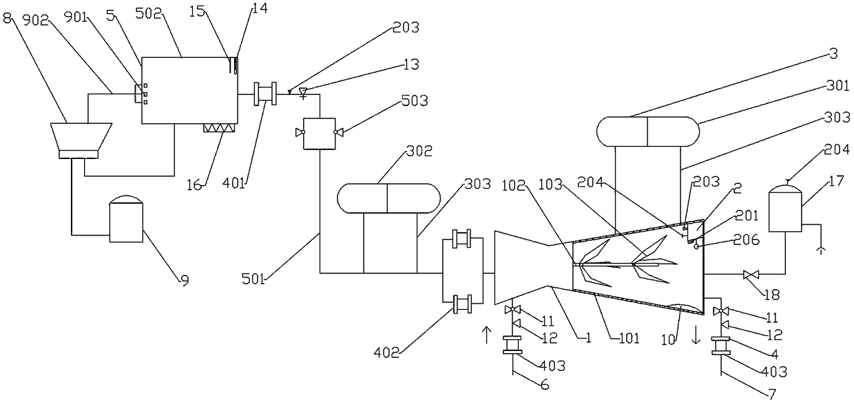
[0035] Such as figure 1 Shown: the protection system of the turbocompressor, including a turbocompressor body 1, the turbocompressor body 1 includes an oil tank 502 connected with an oil outlet pipe 501 and a casing 101, and the casing 101 is provided with a main shaft 102 and an impeller 103 , the impeller 103 is arranged on the main shaft 102; the protection system also includes a monitoring device 2, a cooling device 3, a filtering device 4 and a lubricating device 5, and the monitoring device 2, the cooling device 3, the filtering device 4 and the lubricating device 5 are all connected with the turbine Compressor body 1 connection;

[0036] The monitoring device 2 includes a temperature detector 201, a flow meter 203, a pressure gauge 204 and an axial displacement protection mechanism 206 arranged in the cylinder, and the axial displacement protection mechanism 206 includes an electromagnetic axial displacement transmitter, for example: BSQ031B axial displacement transmit...

Embodiment 2

[0043] On the basis of embodiment 1, further,

[0044] A muffler 10 is arranged inside the turbocompressor body 1 .

[0045] The air inlet of the turbine compressor body 1 is provided with an air intake pipe 6, and the air outlet of the turbine compressor body 1 is provided with an air outlet pipe 7. Both the air inlet pipe 6 and the air outlet pipe 7 are provided with a check valve 11 and a vent valve. valve 12.

Embodiment 3

[0047] On the basis of embodiment 2, further,

[0048] The cooler is a plate cooler.

[0049] The cooler includes an air cooler and a water cooler, the cooling medium in the air cooler is inert gas, and the cooling medium in the water cooler is deionized water.


PUM


Abstract

The invention relates to a protection system of a turbine compressor, and belongs to the technical field of electromechanical equipment control. According to the protection system, a monitoring device, a cooling device, a filtering device and a lubricating device are arranged, so that a turbine compressor body is protected in a targeted mode, and the turbine compressor body stably works by the temperature, the flow and the pressure monitoring; and meanwhile, impurities in lubricating oil and air are effectively prevented from being worn by a compressor unit, so that the purpose of protecting the turbine compressor is achieved, and the requirements of actual electromechanical equipment are met. The protection system is simple in structure, convenient to operate and high in controllability.

Description

technical field [0001] The invention relates to a protection system, in particular to a protection system for a turbine compressor, and belongs to the technical field of electromechanical equipment control. Background technique [0002] A turbo compressor is a machine used to increase gas pressure and transport gas. It is a dynamic compressor with a high-speed rotating impeller. Kinetic energy is obtained, and then the gas flow is decelerated in the diffuser, which converts the kinetic energy into pressure energy, further increasing the pressure, and the gas flow is continuous during the compression process. It is widely used in various processes to transport air and various gases, and to increase its pressure, and the temperature of the gas is also increased accordingly. After multi-stage combination, there is also multi-stage combination of intermediate cooling, and even multi-cylinder combination compression to obtain the final pressure required by the gas. [0003] At ...

Claims


Application Information

Patent Timeline
Patent Type & Authority Applications(China)
IPC IPC(8): F04D25/04F04D27/00F04D29/063F04D29/58F04D29/70
CPCF04D25/045F04D27/001F04D27/008F04D29/063F04D29/582F04D29/701
Inventor 王小龙赵成
Owner DEYANG HONGYUAN ELECTROMECHANICAL ENG
Why Eureka
Try Eureka