Device for composite adsorption microwave recovery or pyrolysis treatment of organic waste gas

A compound adsorption and organic waste gas technology, which is applied in gas treatment, filtration treatment, water/sewage treatment, etc., can solve the problems of increasing air flow resistance, unsatisfactory practical application, and the filter belt is easy to be blocked by pollution, so as to achieve the utilization of resources and energy Effect

Active Publication Date: 2019-02-15
义乌市爱釜义自动化科技有限公司
View PDF5 Cites 2 Cited by
  • Summary
  • Abstract
  • Description
  • Claims
  • Application Information

AI Technical Summary

Problems solved by technology

For example, if a fixed filter belt is used for pretreatment of exhaust gas, the filter belt is easily blocked by dirt, which increases the resistance of the airflow in a short time, and must be stopped for replacement
[0007] In summary, in th

Method used


Image

  • Device for composite adsorption microwave recovery or pyrolysis treatment of organic waste gas
  • Device for composite adsorption microwave recovery or pyrolysis treatment of organic waste gas
  • Device for composite adsorption microwave recovery or pyrolysis treatment of organic waste gas

Examples


Embodiment 1

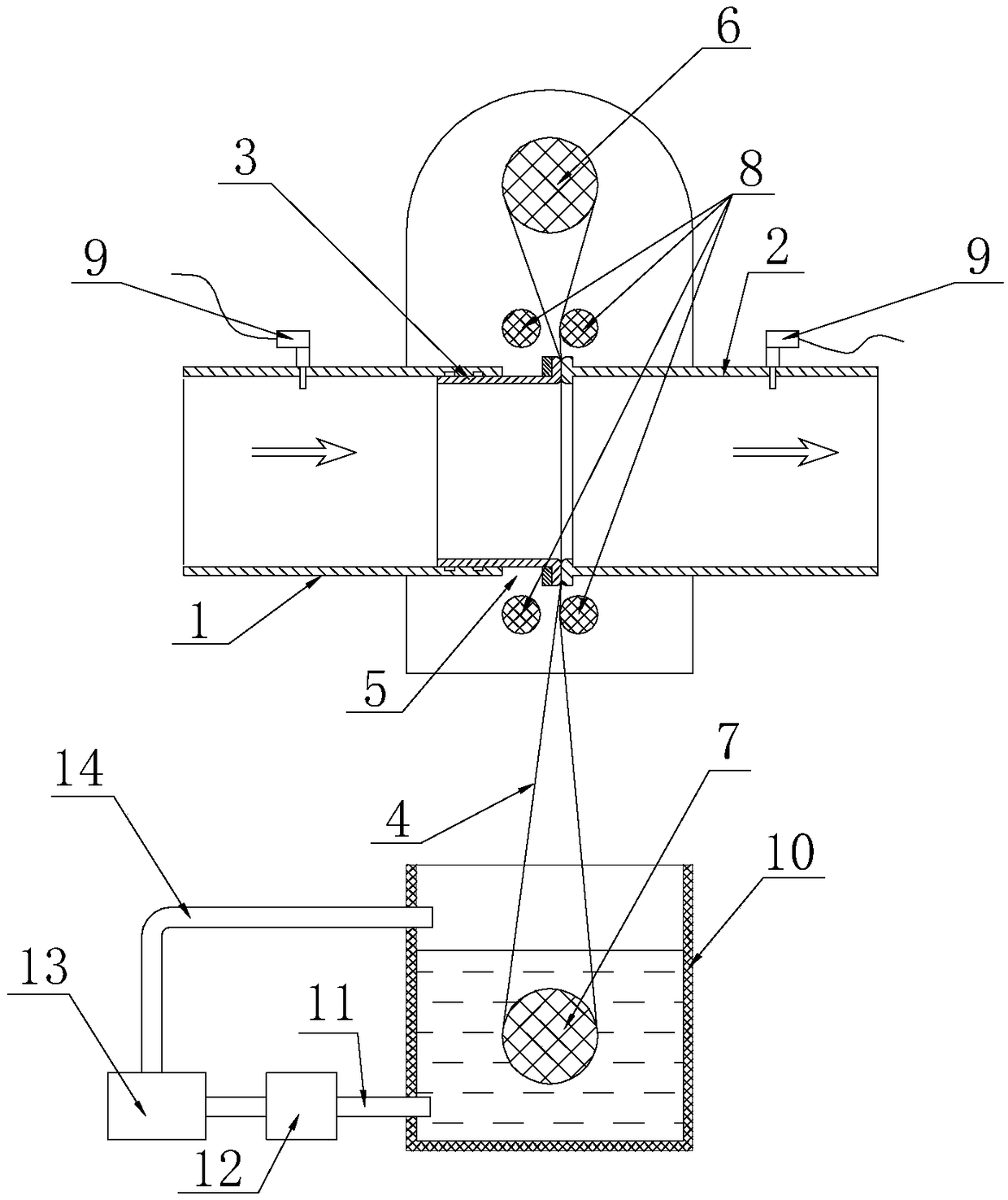
[0092] A device for compound adsorption microwave recovery or pyrolysis treatment of organic waste gas, including a pretreatment unit and a plurality of parallel microwave treatment units.

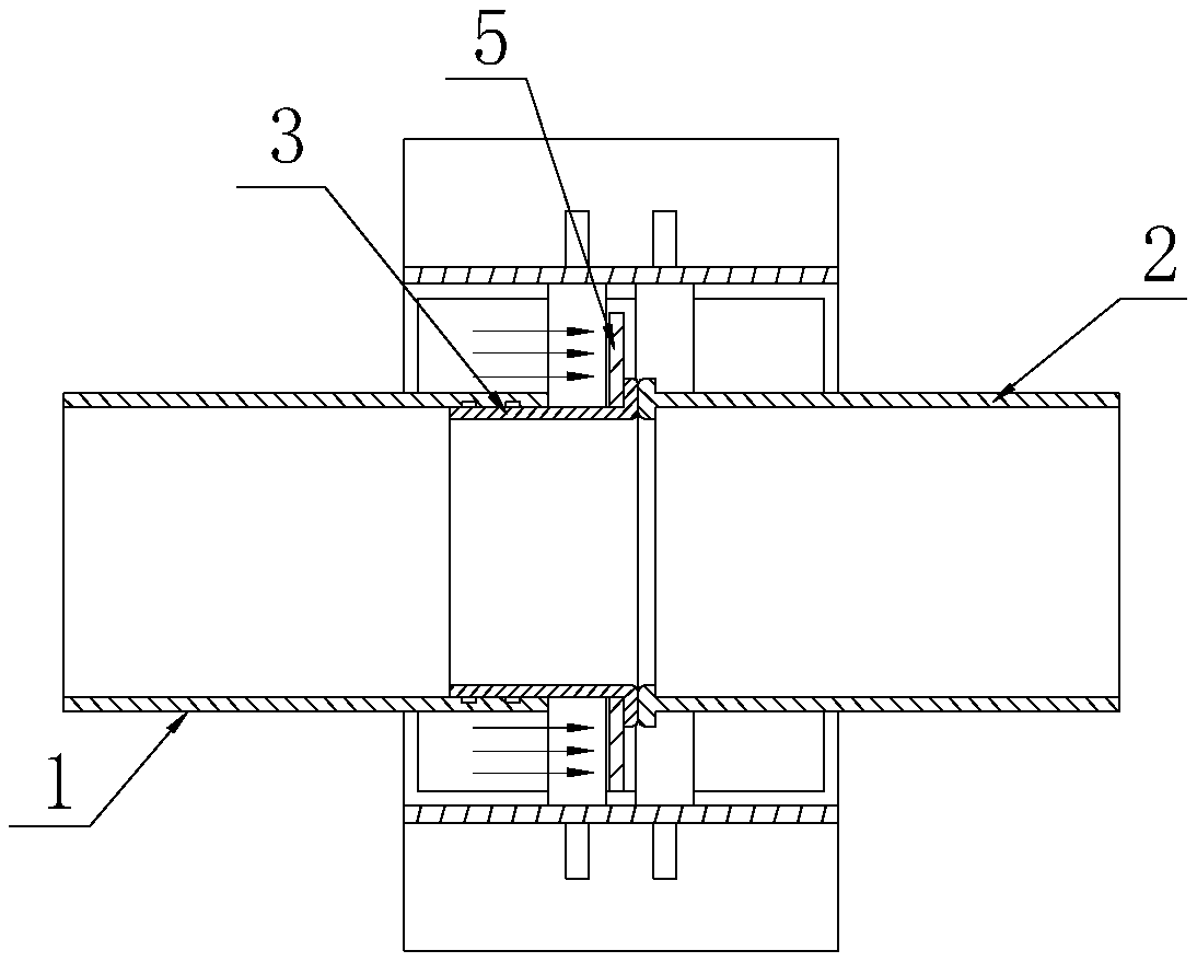
[0093] Such as Figure 1-4 As shown, the pretreatment unit includes a feed pipe 1, a discharge pipe 2, a movable pipe 3, a filter belt 4 (glass fiber filter belt), a circulation transmission mechanism, and a cleaning mechanism; the outlet end of the feed pipe and the discharge pipe The inlet end is opposite to each other, and the movable pipe is arranged between the feed pipe and the discharge pipe.

[0094] The inlet end of the movable pipe is movably socketed with the outlet end of the feed pipe and the outlet end of the movable pipe is opposite to the inlet end of the discharge pipe. The edge of the outlet end of the movable pipe is provided with a pressing plate 5, and the movable pipe is driven by a supporting The mechanism (air cylinder) exerts an external force on the pressure plat...

Embodiment 2

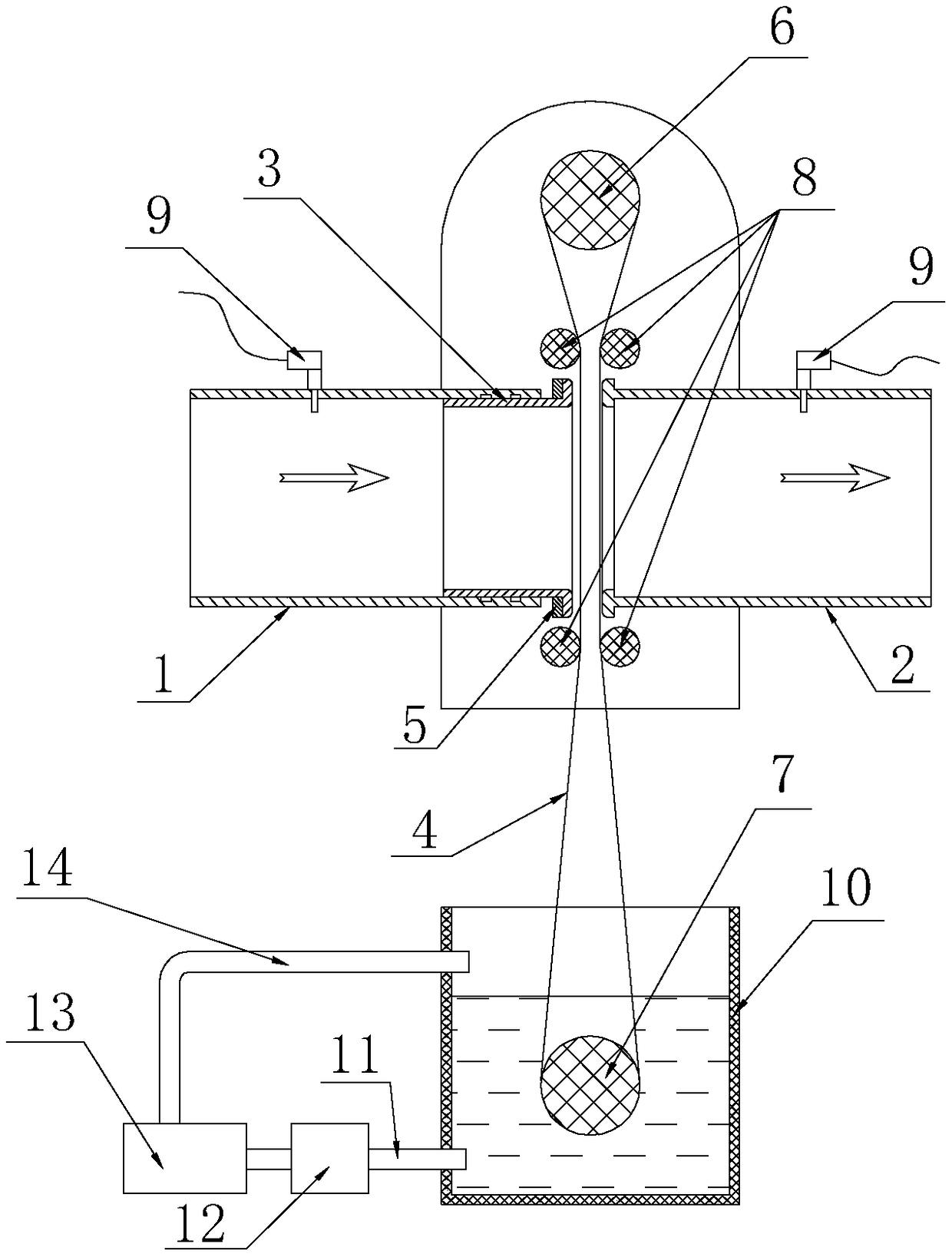
[0113] The difference between this embodiment and Embodiment 1 is that the inlet end of the movable pipe is opposite to the outlet end of the feed pipe and the outlet end of the movable pipe is movably socketed with the inlet end of the discharge pipe; the filter belt is arranged vertically on Circular delivery can be realized between the feed pipe and the active pipe and through the circulation transmission mechanism.

Embodiment 3

[0115] This embodiment adopts the preprocessing unit of scheme two: as Figure 8-10 As shown, it includes a box body 1000, a rolling filter cartridge 1010 and a driving mechanism.

[0116] The box body is provided with an air inlet 1020 and an air outlet 1030; the rolling filter cartridge is provided with a filter cartridge support 1140. The rolling filter cartridge is horizontally arranged in the box body and its two ends are rotatably connected with the box body through bearings 1090 . The rotating surface of the rolling filter cartridge is the filtering surface (stainless steel mesh screen), and one of the end faces of the rolling filter cartridge is provided with an opening to seal and communicate with the air outlet (the opening and the air outlet are provided with a sealing ring 1130 (EVA sealing ring and O-shaped seal) lock up).

[0117] Described driving mechanism comprises motor 1100, motor pulley 1110, rolling pulley 1120 and belt; Described motor pulley is fixed o...


PUM


Abstract

The invention relates to an environmental protection device, and discloses a device for composite adsorption microwave recovery or pyrolysis treatment of organic waste gas. The device comprises a pretreatment unit and a plurality of parallel microwave treatment units; wherein the microwave treatment unit comprises a reaction box, an inlet tube, ceramic tubes, a microwave generator, a connecting tube, an outlet tube and a heat exchanger; the ceramic tubes are arranged in parallel in the reaction box; and the ceramic tubes are filled with active carbon layers and zeolite layers at intervals. Thepretreatment unit can automatically clean a filter medium contaminated. The microwave treatment units have high recovery and pyrolysis efficiency for organic pollutants, and the adsorbent can be repeatedly regenerated for use; and the device is simple, energy-saving, and low in operating cost. The device has great advantages in small and medium-sized volatile organic waste gas recovery and treatment projects.

Description

technical field [0001] The invention relates to the field of environmental protection equipment, in particular to a device for compound adsorption microwave recovery or pyrolysis treatment of organic waste gas. Background technique [0002] Waste gas pollution control is one of the main fields of environmental protection. Volatile organic pollutants (VOCS) are one of the main pollution factors that generate smog, which seriously affects human health and greatly affects people's quality of life. At present, the pollution of VOCS to the environment has been widely concerned. [0003] Currently used VOC treatment technologies such as direct combustion method are only suitable for high-concentration organic waste gas treatment; catalytic combustion method has potential safety hazards; RTO method equipment investment is too large; plasma technology not only has low treatment efficiency but also has potential safety hazards of explosion; ultraviolet light The processing efficienc...

Claims


Application Information

Patent Timeline
IPC IPC(8): B01D46/10B01D46/16B01D53/00B01D53/02C10B53/00C02F1/00C02F103/18
CPCB01D46/10B01D46/16B01D53/007B01D53/02B01D2253/102B01D2253/108B01D2259/40094B01D2259/806C02F1/001C02F2103/18C10B53/00
Inventor 陈德全董永明
Owner 义乌市爱釜义自动化科技有限公司
Why Eureka
Try Eureka