Method and structure for protecting electronic detonator circuit by adopting metal sleeve

A technology of electronic detonators and metal sleeves, which is applied in the direction of offensive equipment, weapon accessories, fuzes, etc., can solve the problems of internal electronic control modules that cannot normally delay ignition, blind firing of detonators, distortion and deformation, etc., to save circuit board space, Reduce the difficulty of production and reduce the effect of components

Pending Publication Date: 2019-02-15
BEIJING QAML OF SCI & TECH CO LTD
View PDF11 Cites 5 Cited by
  • Summary
  • Abstract
  • Description
  • Claims
  • Application Information

AI Technical Summary

Problems solved by technology

There are many quality control measures for the production of electronic detonators. Compared with traditional products, the time delay is accurate and the safety is high. However, in the process of use, it is exposed to the defects of high rejection rate under certain circumstances, especially when the blast hole spacing is less than 30cm. After careful analysis, it is mainly caused by two reasons: one is that the detonation wave, high-pressure gas and high-speed gravel formed by the first-exploded detonator in the detonation delay network, the high-pressure gas and the high-speed gravel act on the detonator body after detonation, squeezing the detonator body The internal electronic control module, which is mainly composed of various electronic components, is not strong enough, and often twists and deforms or even breaks in this case, resulting in blind shots of the detonator; the second is the detonator, explosives and The comprehensive action of rocks will generate strong electromagnetic interference. Such interference is introduced into the electronic detonator by the two legs of the unexploded electronic detonator. The partial discharge of the metal tube also caused the internal electronic control module to fail to delay ignition normally, resulting in blind firing

Method used


Image

  • Method and structure for protecting electronic detonator circuit by adopting metal sleeve
  • Method and structure for protecting electronic detonator circuit by adopting metal sleeve
  • Method and structure for protecting electronic detonator circuit by adopting metal sleeve

Examples


Embodiment 1

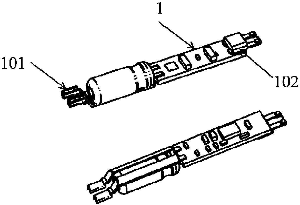
[0033] as attached figure 1 It is a schematic diagram of the electronic control module without shrapnel after the electronic components are mounted, and 101 is the pin line input terminal of the electronic control module, and there are two in total. 102 is a bridge wire terminal for detonating electronic detonator, wherein 102 is completed through surface mount technology together with other electronic components, and 101 is welded to the circuit board by plug-in welding.

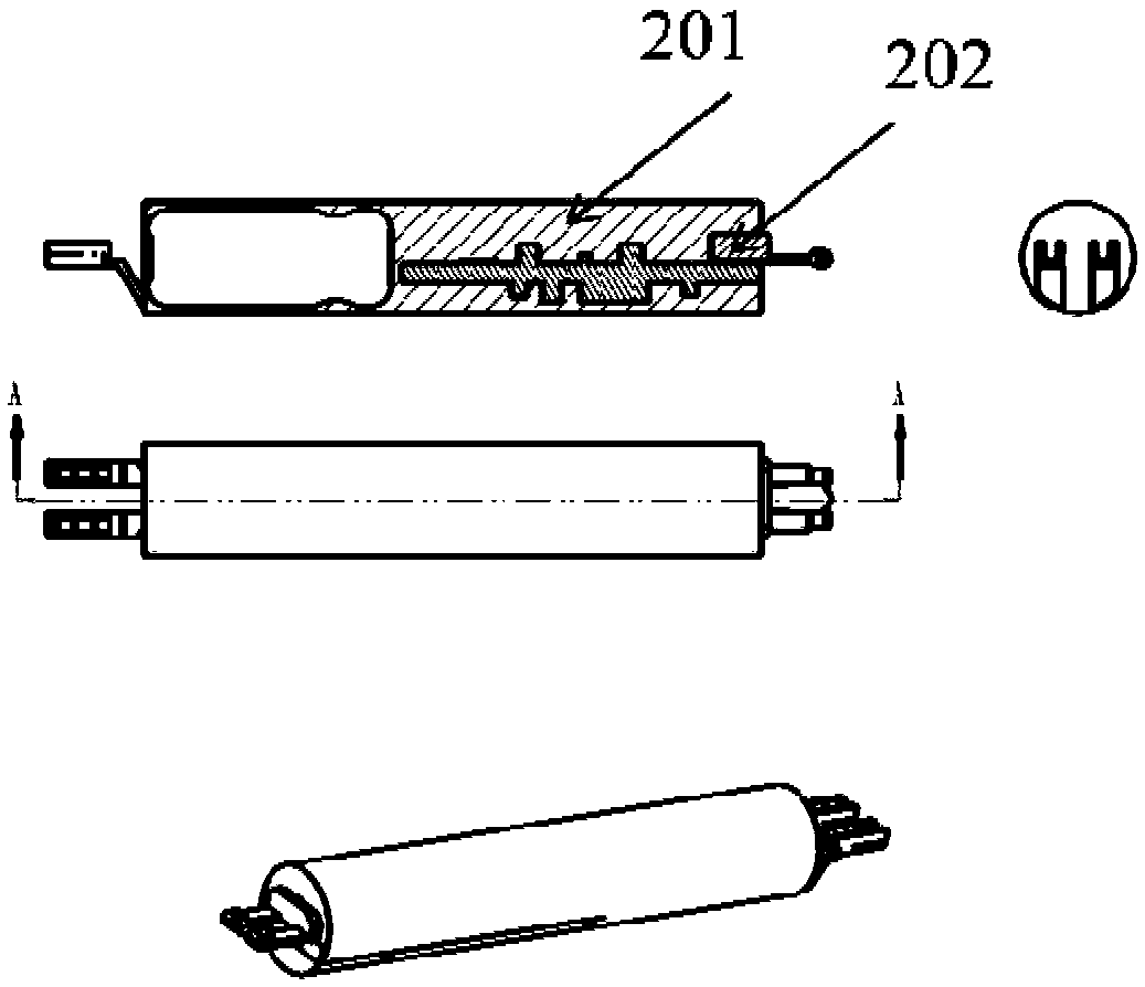
[0034] attached figure 2 It is a schematic diagram of the electronic control module without grounding shrapnel after sealing, in which 201 is the external sealing body. After all the electronic components are mounted, they are placed in a special sealing mold for low-pressure injection molding and sealing, and all the electronic components are packaged into one A regular cylinder, 202 is a circuit board part.

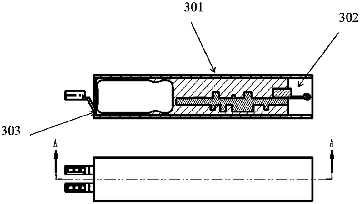
[0035] as attached image 3As shown, the sealed electronic control module is put into the met...

Embodiment 2

[0037] as attached Figure 4 Shown is a product schematic diagram of the electronic control module with grounding shrapnel after the components are mounted, and the implementation of component production is consistent with the embodiment 1 mentioned in the present invention. 401 is the grounding shrapnel, wherein the grounding shrapnel 401 is connected through the contact piece 402 and the inner wall of the metal sleeve. The grounding shrapnel 401 is connected to the circuit board 1 through the connection point B 403, which is completed by welding. The chip capacitor 404 and the chip resistor 405 is installed on the circuit board 1 through surface mount technology, and is connected in series with the ground spring 401. When the sealant 201 encapsulates the circuit board 202, the contact piece 402 leaks out, that is, the ground spring 401 is connected to the inner wall of the metal casing through the contact piece 402. At the same time, it is introduced into the circuit board a...

Embodiment 3

[0041] For the high-density SIP packaging structure, as another technical solution to install the independent control module into the electronic control module, the specific implementation is as follows:

[0042] as attached Figure 7 As shown, the main control chip chip 704, the chip capacitor A 702 and the chip capacitor 703, the chip resistor A 705, and the diode chip 706 are installed on the substrate 701; the chip capacitor A 702 and the chip capacitor 703 are attached. The chip resistor A 705 is installed on the substrate 701 by surface mount technology, and then the main control chip wafer 704 and the diode wafer 706 are fixed on the substrate 701, and then bonded and wired to connect the wafer and the circuit on the substrate 701 connect.

[0043] attached Figure 8 It is a schematic diagram after the overall SIP package is completed, 801 is the leaking pad after the package is completed, 802 is the plastic filler outside the package, and the SIP package is soldered ...


PUM


Abstract

The invention belongs to the technical field of electronic detonator categories in the field of initiating explosive products, and particularly relates to a structure for protecting an electronic detonator control module circuit. According to the structure, a metal sleeve is additionally arranged outside an electronic control module, so that good external acting force protection is provided for the electronic control module; and electromagnetic interference signals generated in the blasting process are shunted to the metal sleeve to be released, so that the purpose of protecting the electroniccontrol module is achieved by adopting the mode, and the phenomenon of misfire generated in the blasting process of an electronic detonator is avoided.

Description

technical field [0001] The invention relates to the technical field of electronic detonators in the field of pyrotechnics, in particular to a method and structure for protecting an electronic detonator circuit by using a metal sleeve. Background technique [0002] Electronic detonators have been widely used in China. Generally, a metal tube with a wall thickness of about 0.3mm is used as the detonator body, and its outer diameter is about 6.5-8mm. The electronic control module is installed in the metal tube and protected by it. There are many quality control measures for the production of electronic detonators. Compared with traditional products, the time delay is accurate and the safety is high. However, in the process of use, it is exposed to the defects of high rejection rate under certain circumstances, especially when the blast hole spacing is less than 30cm. After careful analysis, it is mainly caused by two reasons: one is that the detonation wave, high-pressure gas a...

Claims


Application Information

Patent Timeline
IPC IPC(8): F42C19/12
CPCF42C19/12
Inventor 银庆宇韩延江刘红文
Owner BEIJING QAML OF SCI & TECH CO LTD
Why Eureka
Try Eureka