Supercharge Your Innovation With Domain-Expert AI Agents!

Measuring Method and System for Temperature Deformation of Piezoelectric Composite Materials

A piezoelectric composite material and testing method technology, applied in measurement devices, instruments, optical devices, etc., to achieve the effect of promoting design and preparation process, promoting improvement, and improving environmental adaptability

Inactive Publication Date: 2019-02-15
BEIJING INFORMATION SCI & TECH UNIV
View PDF9 Cites 6 Cited by
  • Summary
  • Abstract
  • Description
  • Claims
  • Application Information

AI Technical Summary

Problems solved by technology

[0013] The invention provides a method and system for testing temperature deformation of piezoelectric composite materials to solve the problem of accurate quantitative testing of temperature deformation of piezoelectric composite materials

Method used


Image

  • Measuring Method and System for Temperature Deformation of Piezoelectric Composite Materials
  • Measuring Method and System for Temperature Deformation of Piezoelectric Composite Materials
  • Measuring Method and System for Temperature Deformation of Piezoelectric Composite Materials

Examples


Embodiment 1

[0041] Example 1: Test method for temperature deformation of piezoelectric composite materials

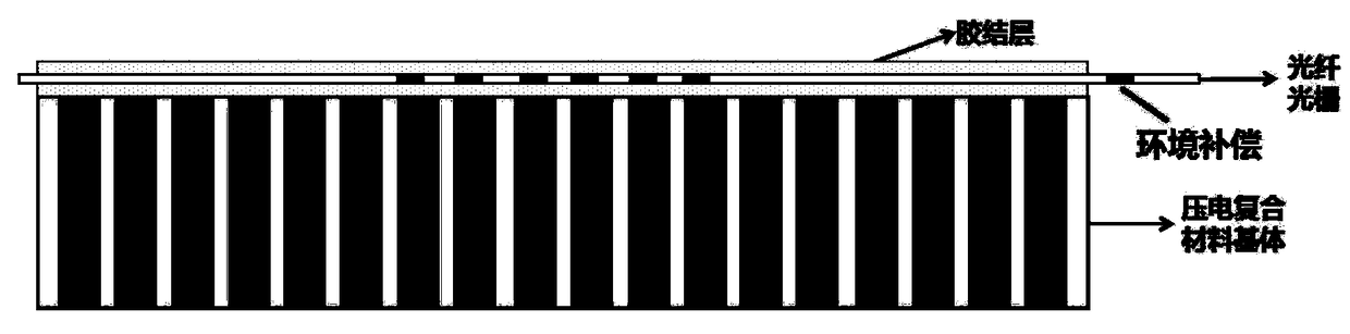
[0042] A fiber grating is a diffraction grating formed by periodically modulating the refractive index of the fiber core through a certain method. The common method is to use the photosensitivity of the optical fiber material to write the coherent field pattern of the incident light into the fiber core by means of ultraviolet light exposure, and produce a periodic change in the refractive index along the axis of the fiber core in the fiber core, thereby forming a permanent space. Phase grating, its function is to form a narrow-band (transmission or reflection) filter or mirror in the fiber core.

[0043] The relationship between the wavelength change of the fiber grating reflected light and the strain is as follows:

[0044]

[0045] Among them, λ is the wavelength of the light reflected by the FBG, Δλ is the wavelength change of the light reflected by the FBG, ε is the axial str...

Embodiment 2

[0059] Example 2: Testing System for Temperature Deformation of Piezoelectric Composite Materials

[0060] This embodiment provides a test system for temperature deformation of piezoelectric composite materials using the above method. The composition and connection relationship of the test system are as follows: Figure 4 shown. The function description of each part is as follows:

[0061] High and low temperature test box; used to create a use environment where the temperature of the piezoelectric composite material itself rises;

[0062] Demodulator: used to monitor the wavelength of the reflected light of the fiber grating;

[0063] Impedance analyzer: used to measure performance parameters such as resonance frequency and capacitance of piezoelectric composite materials;

[0064] Computer: It is used to calculate, analyze and process the test data obtained by the demodulator and impedance analyzer, and obtain the strain value and deformation value.


PUM


Abstract

The invention relates to a measuring method and system for temperature deformation of piezoelectric composite materials. The method attaches the fiber with grating to the piezoelectric composite material to be tested; monitors the wavelength of the reflected light of the fiber grating; calculates the strain of the fiber grating according to the relationship between the wavelength change of the reflected light of the fiber grating and the strain of the fiber grating, which is the strain of the piezoelectric composite material to be tested. The method leaves at least one grating for environmental compensation. The grating used for environmental compensation is not closely attached to the piezoelectric composite material, so that the strain change is only affected by the environmental change.According to the requirement of quantitative measurement of temperature deformation of piezoelectric composite materials, a method of measuring temperature deformation of piezoelectric composite materials by using a fiber grating sensing method is proposed, which breaks through the key technologies of precision control and real-time data acquisition for quantitative measurement of temperature deformation of piezoelectric composite materials, and solves the problem of accurate quantitative measurement of temperature deformation of piezoelectric composite materials.

Description

technical field [0001] The invention belongs to the field of transducer technology and piezoelectric composite material technology, and in particular relates to a testing method and system for temperature deformation of piezoelectric composite material. Background technique [0002] As the largest area that has not been fully developed and utilized on the earth, the ocean has great potential to solve the contradictions in population, resources and environment. Technologies such as underwater communication, underwater early warning, and underwater guidance systems require the support of advanced sonar systems. As the "eyes and ears" of the sonar system, the transducer is similar to the antenna in the radar. With the rapid development of modern large-scale integrated circuits, the signal processing technology has become more and more perfect, and the important factor restricting the development of sonar is the development level of the transducer. Among them, a type of high-f...

Claims


Application Information

Patent Timeline
IPC IPC(8): G01B11/16
CPCG01B11/18
Inventor 王丽坤廖擎玮白智奇康冰琳仲超秦雷
Owner BEIJING INFORMATION SCI & TECH UNIV
Features
  • R&D
  • Intellectual Property
  • Life Sciences
  • Materials
  • Tech Scout
  • Unparalleled Data Quality
  • Higher Quality Content
  • 60% Fewer Hallucinations
Learn More