
Dust removal heat exchange white elimination device and system

A whitening and equipment technology, applied in the direction of electrostatic effect separation, solid separation, and dispersed particle separation, etc., can solve the problems that the use of space cannot be fully utilized, affect the stability of system operation, and heat exchange tubes are easy to pile up dust, etc., to achieve water vapor The effects of content reduction, flow rate reduction, and floor area reduction

Pending Publication Date: 2019-03-01
FUJIAN LONGKING
View PDF0 Cites 7 Cited by
  • Summary
  • Abstract
  • Description
  • Claims
  • Application Information

AI Technical Summary

Problems solved by technology

Using the principle of gas-gas heat exchange, it solves the problems of installing flue gas coolers, air coolers and flue gas heaters outside the tower, which occupy a large area and high operating costs.
However, the inner wall of the heat exchange tube is easy to accumulate dust during operation, which affects the stability of the system operation; and the heat exchange tube in the heat exchanger is only used for heat exchange, and the use of space cannot be fully utilized

Method used


Image

  • Dust removal heat exchange white elimination device and system
  • Dust removal heat exchange white elimination device and system
  • Dust removal heat exchange white elimination device and system

Examples


Embodiment Construction

[0033] In order to enable those skilled in the art to better understand the technical solutions of the present invention, the present invention will be further described in detail below in conjunction with the accompanying drawings and specific embodiments.

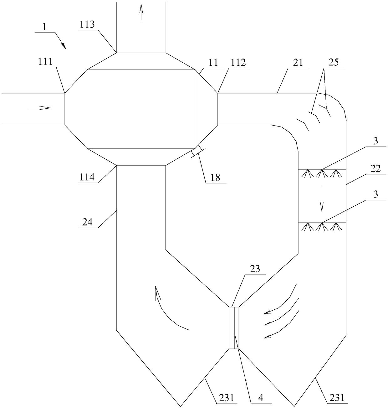
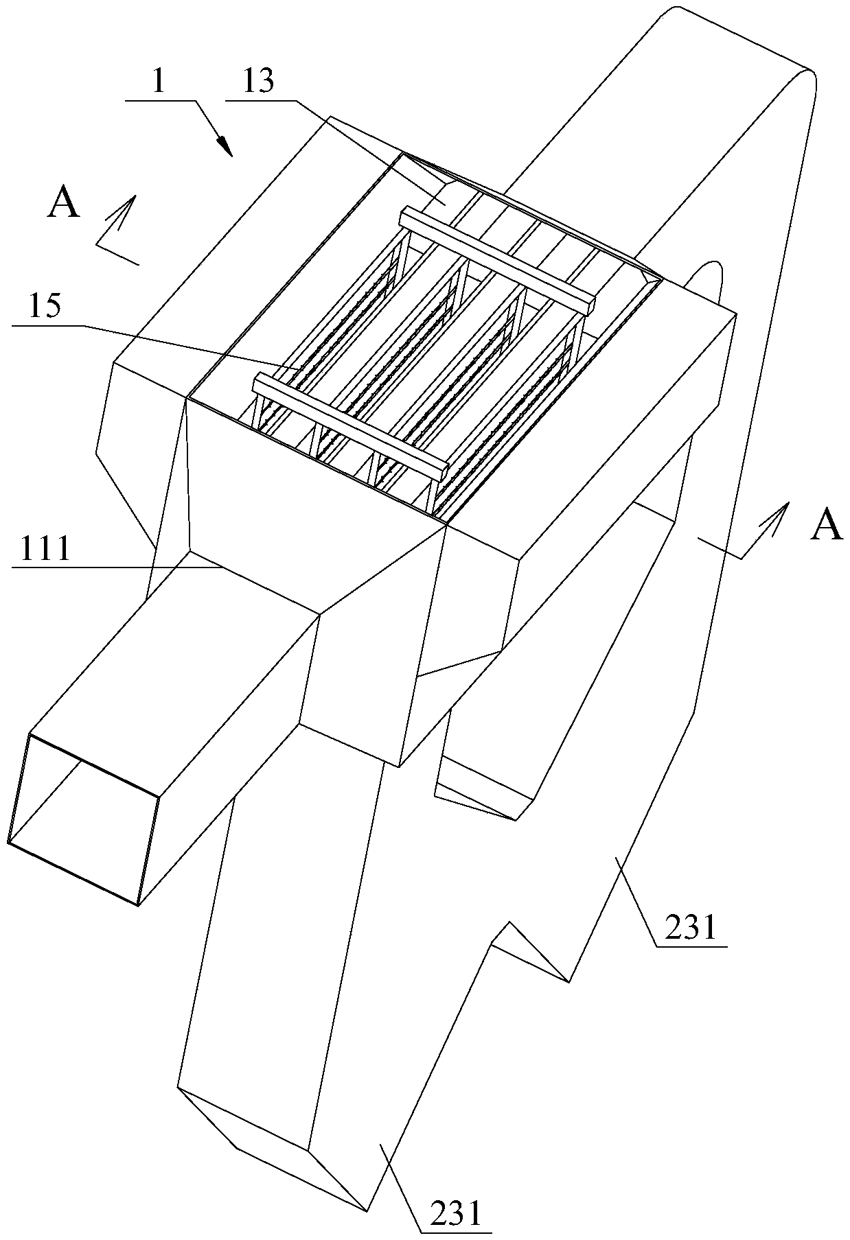
[0034] The core of the dust removal, heat exchange and whitening system provided in this embodiment is to make full use of the internal space and highly integrate the functional components of dust removal and whitening. On the basis of reducing the system footprint and equipment manufacturing cost, it has a better energy-saving effect. Without loss of generality, this embodiment uses figure 1 The dust removal, heat exchange and whitening system shown in the figure is the main body of the basic description. It should be understood that the arrangement of the internal circulation treatment flue of the system is not limited to the form shown in the figure, and its parallel flue and vertical flue are not constitutive of this s...


PUM


Abstract

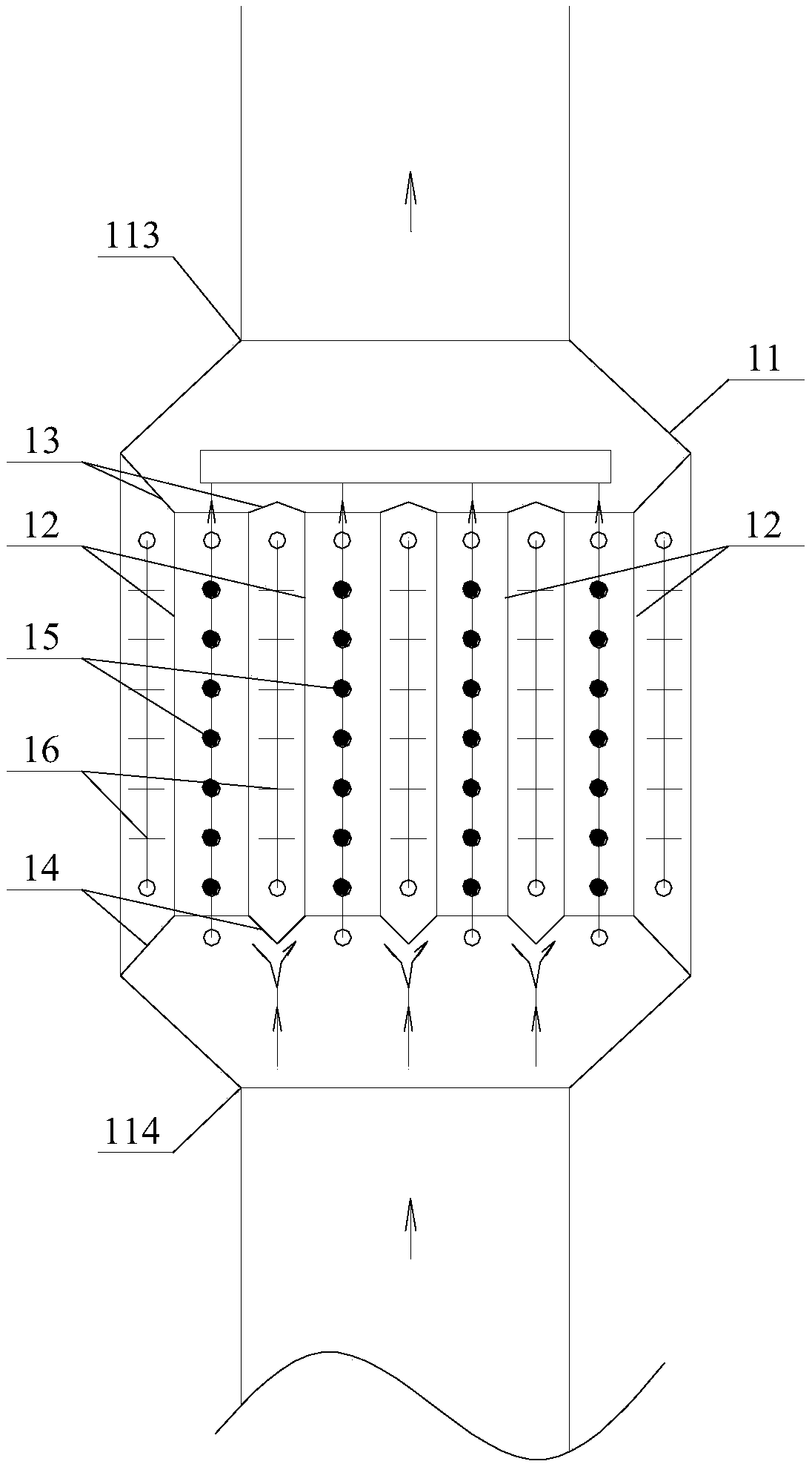
The invention discloses a dust removal heat exchange white elimination device and system. A plurality of dust collection heat exchange cylinders are vertically arranged in a device casing. A verticalpassage from an inner circulation inlet to an exhaust outlet is formed in the inner cavity of each dust collection heat exchange cylinder. A horizontal passage from an exhaust inlet to an inner circulation outlet is formed between every two adjacent dust collection heat exchange cylinders. Upper and lower partitions connected in the sealing mode are utilized to ensure that flue gas flows between the horizontal passages and the vertical passages which are independently sealed without interference. Therefore, high-temperature high-humidity exhaust gas can complete heat exchange in the device with low-temperature exhaust gas subjected to internal circulation treatment. At the same time, a plurality of sets of first cathode lines are arranged laterally in the dust collection heat exchange cylinders to form a high voltage electric field with the inner walls of the dust collection heat exchange cylinders. Second cathode lines are arranged between the adjacent dust collection heat exchange cylinders and between the dust collection heat exchange cylinders on two sides and the inner wall of the casing to form the high voltage electric field with the outer walls of the dust collection heat exchange cylinders. A cleaning nozzle is disposed above an upper partition. The device has a good dust removal and white elimination effect.

Description

technical field [0001] The invention relates to the technical field of industrial production emission treatment, in particular to a dust removal, heat exchange and whitening equipment and system. Background technique [0002] The tail gas emitted by industrial production has a high temperature, high dust content and high moisture content. It will directly enter the tail gas treatment equipment without treatment, which will increase the equipment load, increase power consumption and water consumption, and lead to increased operating costs. At the same time, the outlet exhaust gas after pollutant treatment has low temperature and high moisture content, and the saturated gas will be cooled sharply when encountering the lower temperature atmosphere, and the water vapor in the flue gas will condense into a liquid state, forming a white plume; especially in winter, affect the beauty of the environment. In response to the above problems, flue gas heat exchange technology is usuall...

Claims


Application Information

Patent Timeline
IPC IPC(8): B03C3/017B01D53/26
CPCB01D53/265B03C3/017
Inventor 叶兴联周宗勇芦佳杨丁郑好陈炳余詹秋月
Owner FUJIAN LONGKING
Learn More