Novel non-destructive testing method for bridge pile foundation

A non-destructive testing and pile foundation technology, applied in the direction of foundation structure engineering, foundation structure test, construction, etc., can solve the problems of quantitative detection of defective parts, etc., and achieve the effect of accurate analysis and high sensitivity

Inactive Publication Date: 2019-03-01
TONGREN UNIV
View PDF6 Cites 2 Cited by
  • Summary
  • Abstract
  • Description
  • Claims
  • Application Information

AI Technical Summary

Problems solved by technology

[0004] The purpose of the present invention is to solve the problem that the quantitative detection of defect

Method used


Image

  • Novel non-destructive testing method for bridge pile foundation
  • Novel non-destructive testing method for bridge pile foundation
  • Novel non-destructive testing method for bridge pile foundation

Examples


Embodiment 1

[0049] A new non-destructive testing method for bridge pile foundations, comprising the following steps;

[0050] S1. Use a hammer to tap the upper part of the pile foundation, and collect reflected wave data through the sensor installed on the upper part of the pile foundation;

[0051] S2. Bring the data collected in S1 into the following formula for analysis, and create a waveform diagram for analysis and comparison;

[0052]

[0053] In the formula: Particle vibration displacement; The distance from the particle vibration to the vibration source; time of particle vibration; damping coefficient; cross-sectional area of ​​the pile; The velocity of longitudinal waves propagating in the pile ; mass density of the pile;

[0054] When a momentary external force is applied to the top of the pile When , there are only downgoing waves in the pile, and the waves are reflected on different wave impedance surfaces. From the above formula, the travel time of the st...

Embodiment 2

[0064] Embodiment 2: the difference based on Embodiment 1 is;

[0065] S5 ultrasonic CT model establishment, including the following steps;

[0066] A1, the data measured in S4 is brought into the following formula, and the ultrasonic imaging discrete model is established by adopting;

[0067]

[0068] In the formula: for the first The time it takes for a sound wave to travel along the propagation path.

[0069] A2. Transform the model in A1 into an acoustic wave model, discretize the test area with an equidistant grid, and set the ultrasonic velocity distribution in each grid unit to:

[0070] .

[0071] In the formula: diameter; velocity gradient; constant; and use high-precision ray tracing to solve the forward modeling problem;

[0072] A3. Through tomographic inversion, it is assumed that the number of travel time data of ultrasonic waves measured in the measured area is , the discrete model parameters of the measured area There is the following nonl...

Embodiment 3

[0076] Embodiment 3: the difference based on embodiment 1 and 2 is;

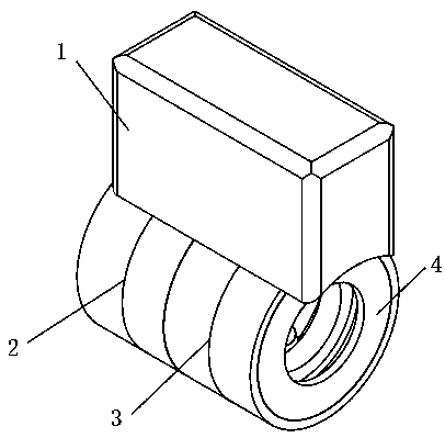
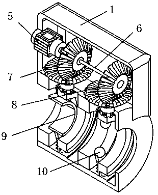
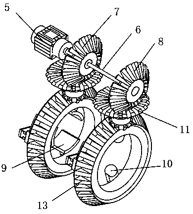
[0077] A new type of nondestructive testing device for bridge pile foundations, which is applied to a new type of nondestructive testing method for bridge pile foundations, including a fixed housing 1, a CT measuring device 3, and a driving device 2. The CT measurement device 3 is fixedly installed on the front side of the lower end of the housing 1, and the driving motor 5 is fixedly installed inside the fixed housing 1. The front end of the driving motor 5 is fixedly connected to the rear end of the rotating shaft 6, and the rear end of the rotating shaft 6 is fixedly connected to the axis center of the rotating gear 7. , the rear end of the rotating shaft 6 is fixedly connected to the axis of the transmission gear 8 , and the rotating gear 7 and the transmission gear 8 are engaged with the CT measuring device 3 and the upper end of the driving device 2 .

[0078] Both the CT measuring device 3 and the dri...


PUM


Abstract

The invention discloses a novel non-destructive testing method for a bridge pile foundation and belongs to the field of bridge pile foundation detection. When analyzing the pile foundation detection data, the pile foundation defect is judged by the average of the health time and twice the standard deviation. According to the half value of the amplitude mean M, whether a lesion occurs in the pile foundation or not is determined. If the pile foundation stress wave changes the peak size and the peak appearance time, the bridge pile foundation may have different degrees of cracks or gaps. If a crack occurs inside the pile foundation, the stress wave propagation characteristics at the crack should be correspondingly changed, so that the reflected wave disturbance may occur. Non-destructive detection will not damage the quality and structure of the pile, especially when detecting the integrity of the bridge pile foundation, and the detection can be used to maximize efficiency. The stress wave method is theoretically mature and can accurately analyze the integrity of the pile foundation.

Description

technical field [0001] The invention relates to the field of bridge pile foundation detection, in particular to a novel non-destructive detection method for bridge pile foundations. Background technique [0002] With the rapid growth of the national economy, public construction has also been showing a rapid growth trend. In public construction, the transportation industry has been vigorously developed, and a large number of bridges need to be built. my country's bridges generally use pile foundations. The pile foundation is located under the ground and is relatively hidden. Factors such as geological conditions and construction technology can easily cause damage to its structure. Non-destructive testing technology can directly detect whether there are quality problems such as pores and cracks in the pile foundation, and can also check whether the construction technology meets the project quality requirements. Not only is the detection method safe, but it also has the chara...

Claims


Application Information

Patent Timeline
IPC IPC(8): E02D33/00
CPCE02D33/00
Inventor 朱崇利董云
Owner TONGREN UNIV
Why Eureka
Try Eureka