Photoelectric composite test sensor and manufacturing method thereof
A photoelectric composite and sensor technology, which is applied in radio wave measurement systems, re-radiation of electromagnetic waves, devices that measure the time required to move a certain distance, etc. The time information of the specific location of the feature and other issues can achieve the effect of accurate data reference, reducing the test space and overcoming the limitations.
- Summary
- Abstract
- Description
- Claims
- Application Information
AI Technical Summary
Problems solved by technology
Method used
Image
Examples
Embodiment 1
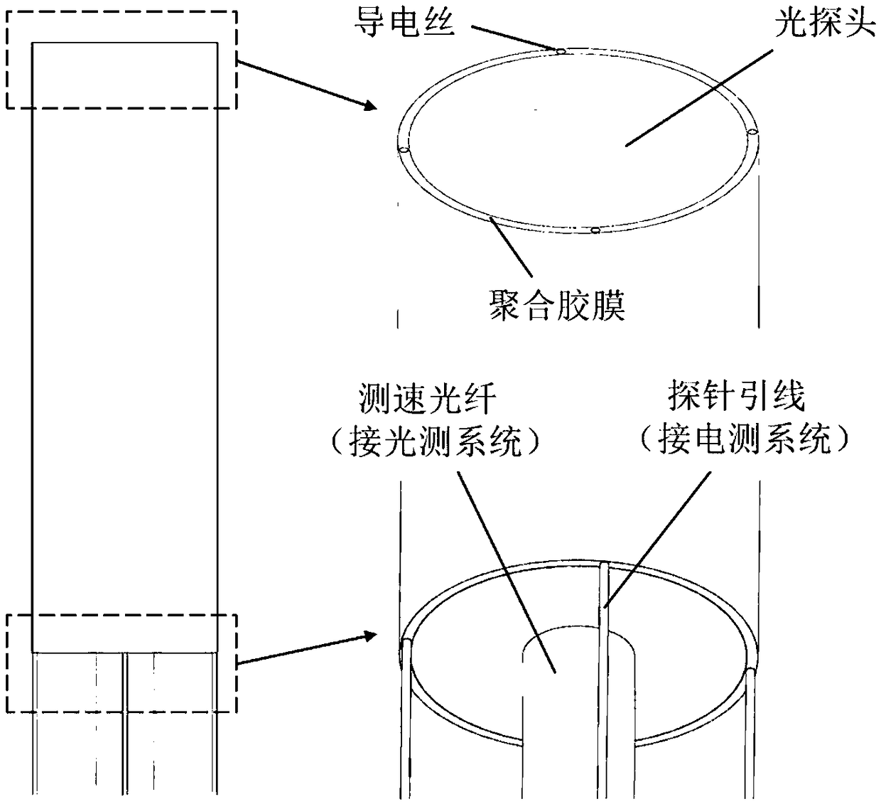
[0022] A photoelectric composite test sensor, the sensor is composed of an electric probe and a laser speed measuring probe, the electric probe is composed of a conductive wire and a polymer film, and the conductive wire is uniformly cured on two layers with an adhesive Between the hot-melt polymer film, the number of conductive wires is evenly distributed on the circumference of ≥2, and the part of the conductive thread exposed outside the polymer film is coated with insulating varnish. The electric probe is uniformly coated on the surface of the laser speed measuring probe, the laser speed measuring probe includes an optical fiber probe and a speed measuring optical fiber, the optical fiber probe is arranged on the top of the speed measuring optical fiber, and the end face of the electric probe is higher than the optical fiber The end face of the probe, the tail of the speed-measuring optical fiber is connected to the optical measurement system, and the tail end of the conduc...
Embodiment 2
[0024] A kind of preparation method of photoelectric compound test sensor, sensor comprises electrical probe (conductive wire, polymer film) and laser velocity measuring probe (optical probe, velocity measuring optical fiber) two parts, such as figure 1 shown. In the process of sensor production, special fixtures are used to evenly distribute and solidify conductive wires (number ≥ 2, to ensure reliability) between two layers of hot-melt polymer films through adhesives. The probe has the characteristics of high electrical insulation, corrosion resistance, and good thermal stability. Subsequently, with the help of a special reel and shaping process, the polymer film containing the conductive thread is evenly coated on the surface of the optical fiber probe, and the outer surface of the conductive thread exposed outside the polymer film is coated with insulating varnish. In order to prevent the optical fiber probe from affecting the test of the electrical probe, ensure that the...
Embodiment 3
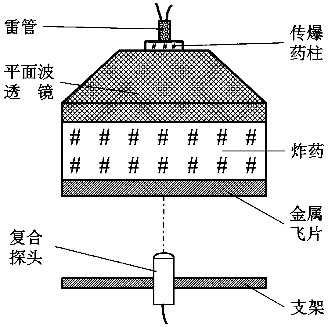
[0026] Taking the application of the photoelectric composite test sensor in the metal flyer detonation loading experiment as an example, its use method is further explained.
[0027] Such as figure 2 As shown, the experimental device is composed of a detonator, a booster charge, a plane wave lens, explosives, and a metal flyer. At a certain distance from the metal flyer, the photoelectric composite test probe is fixed with a bracket, and the probe is facing the metal flyer. The speed-measuring optical fiber of the composite probe and the lead wire of the electrical probe are respectively connected to the optical measurement system and the electrical measurement system. In the detonation experiment, the plane wave lens is detonated by the detonator, which is transmitted to the cylindrical explosive synchronously to generate a plane detonation wave, which drives the metal flyer to move towards the composite probe. When the detonator is detonated, both the electrical measuremen...
PUM
 Abstract
Description
Claims
Application Information
 - R&D
- Intellectual Property
- Life Sciences
- Materials
- Tech Scout
- Unparalleled Data Quality
- Higher Quality Content
- 60% Fewer Hallucinations
Browse by: Latest US Patents, China's latest patents, Technical Efficacy Thesaurus, Application Domain, Technology Topic, Popular Technical Reports.
© 2025 PatSnap. All rights reserved.Legal|Privacy policy|Modern Slavery Act Transparency Statement|Sitemap|About US| Contact US: help@patsnap.com


