
Temperature control system

A technology of temperature control system and control components, which is applied in the direction of electrical components, thermal switch components, power devices inside the switch, etc., can solve the problems of high maintenance cost, high technical requirements, high price, etc., and achieve high control accuracy, The effect of wide control range and low power consumption

Inactive Publication Date: 2019-03-01
CHONGQING THREE GORGES UNIV
View PDF3 Cites 4 Cited by
  • Summary
  • Abstract
  • Description
  • Claims
  • Application Information

AI Technical Summary

Problems solved by technology

[0003] At present, most of the temperature control systems are basically based on the temperature detection module and the single-chip microcomputer control system to control the temperature. interference

Method used


Image

  • Temperature control system
  • Temperature control system
  • Temperature control system

Examples


Embodiment 1

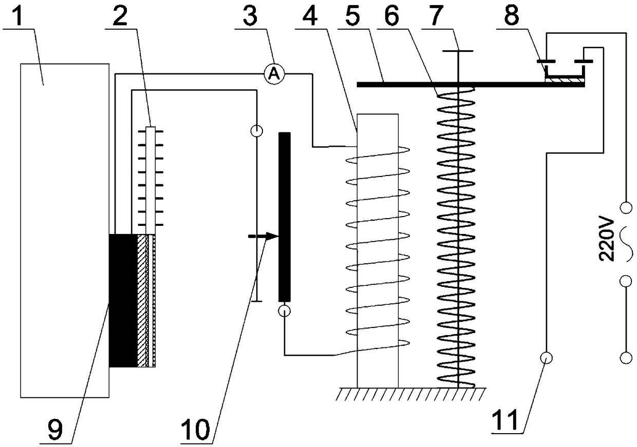
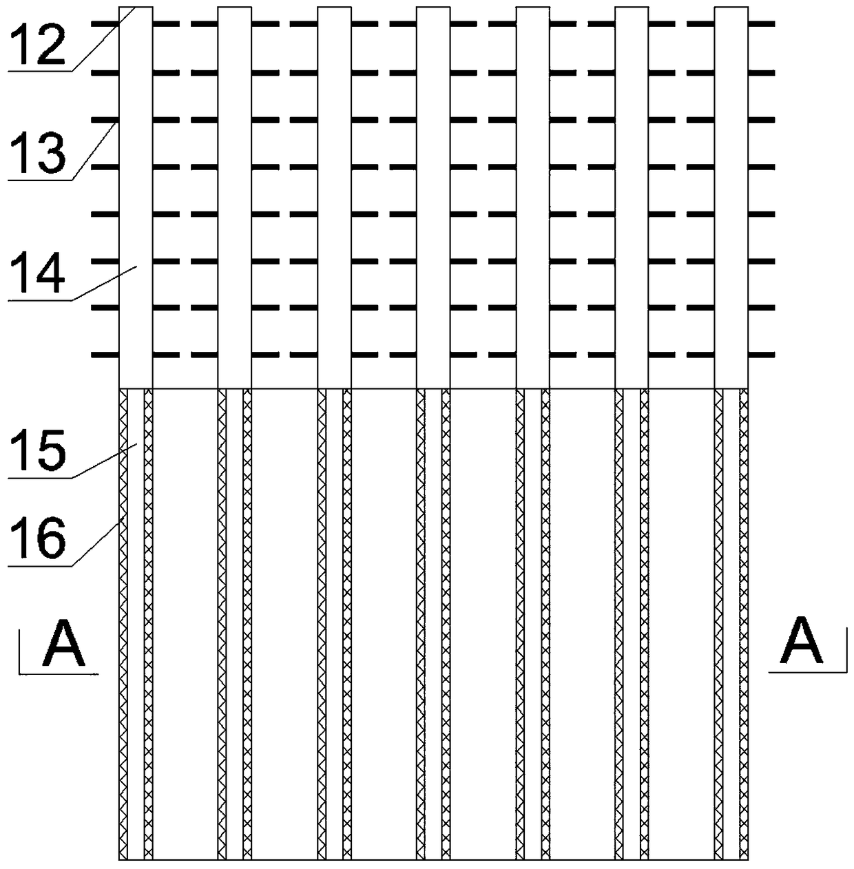
[0027] Such as Figure 1-Figure 3 As shown, the embodiment of the present invention includes a thermoelectric chip 9 , an electromagnet 4 , an armature 5 and a vacuum heat pipe cooling system 2 .

[0028] The hot end of the thermoelectric chip 9 is placed at the place to be detected 1, and the cold end dissipates heat through the vacuum heat pipe system 2. The thermoelectric chip 9 is closed and communicated with the electromagnet 4, and the electromagnet 4 is aligned with the armature 5. The active end is set, and the driven end of the armature 5 is insulated and provided with a control element 8 connected to an external circuit. The control element 8 is a normally closed contact switch, that is, the contact switch is fixed on the driven end of the armature 5 through insulating glue. When the hot end of the thermoelectric generation piece 9 senses that the temperature at the place to be detected reaches the set temperature, the thermoelectric generation piece generates a magn...

Embodiment 2

[0035] Such as Figure 4 As shown, compared with the technical solution in embodiment 1, in this embodiment, the contact switch in embodiment 1 is replaced with an external rheostat, specifically a sliding rheostat for an external circuit. A system that connects the circuit to make real-time corresponding feedback, such as a heating system or a water heater constant temperature control system. After the temperature difference heating plate detects the temperature to be detected, it feeds back to the external circuit in real time, and the external circuit adjusts the power to achieve the effect of constant temperature. Of course, as known by those skilled in the art, the external electrical components in this technical solution are not only contact switches or external sliding rheostats, but also other systems that require feedback based on temperature detection, which are also applicable.


PUM


Abstract

The invention discloses a temperature control system device, and relates to the field of temperature control equipment. The temperature control system device mainly comprises a thermoelectric power generation piece, an electromagnet and an armature; the hot end of the thermoelectric power generation piece is arranged at a position to be detected; the thermoelectric power generation piece is in close communication with the electromagnet, and the electromagnet is aligned with the driving end of the armature; the driven end of the armature is provided with a control element connected with an external circuit in an insulating mode; when the hot end of the thermoelectric power generation piece senses that the temperature in the position to be detected reaches the set temperature, the electromagnet provides a current to reach a set requirement, and the electromagnet attracts the driving end of the armature to move; and the driven end of the armature also moves to enable a control element switch connected with a contact external connection circuit to be opened or closed or adjusted; and simple structure, low cost, wide regulation range, high control precision and low electric energy consumption are achieved.

Description

technical field [0001] The invention relates to a temperature control system, and mainly relates to the field of temperature control equipment. Background technique [0002] With the shortage of energy and people's increasing awareness of environmental protection, especially the problem of global warming, semiconductor thermoelectric power generation technology and its various advantages have attracted people's attention. With the rapid development of current social technology, thermoelectric power generation technology has been greatly improved. The principle of thermoelectric power generation, as the name implies, is to use temperature difference to generate voltage and current. According to the principle of Seebeck effect, when the Seebeck coefficients of the two materials do not change with temperature, the potential difference of thermoelectric power generation changes linearly with the temperature difference, that is, the greater the temperature difference, the greate...

Claims


Application Information

Patent Timeline
IPC IPC(8): H01H3/28H01H37/02H02N11/00
Inventor 陈才张波涛刘利利程龙飞郭远臣周廷强胡科
Owner CHONGQING THREE GORGES UNIV
Learn More