Flexible display panel and preparation method thereof

A flexible display and flexible substrate technology, which is applied in semiconductor/solid-state device manufacturing, semiconductor devices, electrical components, etc., can solve the problems of difficult to guarantee the shear force of the film layer, large difference in bending ability, and increased maximum strain, etc., to achieve Improve bendability and service life, avoid film layer separation, and increase adhesion

Active Publication Date: 2020-07-31
GUANGZHOU GOVISIONOX TECH CO LTD
View PDF4 Cites 0 Cited by
  • Summary
  • Abstract
  • Description
  • Claims
  • Application Information

AI Technical Summary

Problems solved by technology

In practical applications, the flexible display panel is usually bent. When the flexible display panel is curled or unfolded, the materials of the touch layer 30 ′ and the POL layer 40 ′ of the flexible display panel are different, and the bending ability is quite different. The continuous application of stress will cause the separation of the touch layer 30' and the POL layer 40' of the OLED device, causing physical and structural damage to the OLED display panel and causing separation from each other, which makes it difficult to guarantee the performance of the flexible OLED display device
[0005] Aiming at the above-mentioned problem that the touch layer and the POL layer attached to each other in the flexible display panel are easy to separate from each other, a solution in the prior art is to coat a thicker optical glue between the touch layer and the POL layer to Increase the bonding force between the two film layers, thereby reducing the possibility of separation of the two film layers. However, this method will make the entire flexible display panel thicker, which will increase the maximum strain suffered during the bending process. The bending stress of each film layer is also relatively high, which makes the effect of preventing the separation of the touch layer and the POL layer not good
Another solution in the prior art is to add an interlocking structure or increase the roughness of the surface between the touch layer and the POL layer to prevent the two from being separated from each other. hard to guarantee

Method used


Image

  • Flexible display panel and preparation method thereof
  • Flexible display panel and preparation method thereof
  • Flexible display panel and preparation method thereof

Examples


Embodiment Construction

[0034] The present invention will be described in detail below in conjunction with various embodiments shown in the drawings. However, these embodiments do not limit the present invention, and any structural, method, or functional changes made by those skilled in the art according to these embodiments are included in the protection scope of the present invention.

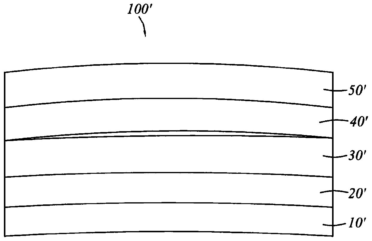
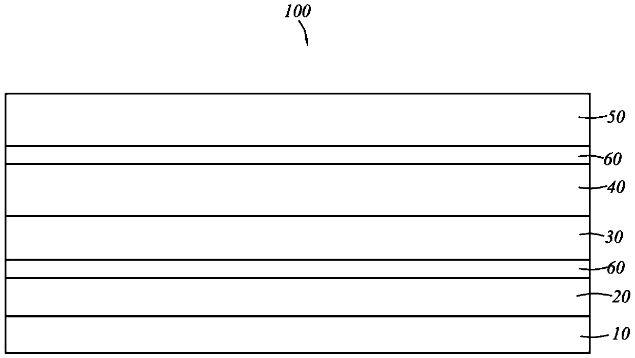
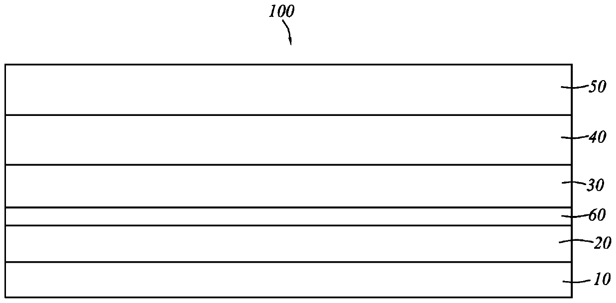
[0035] Please refer to Figure 2 to Figure 4 As shown, the flexible display panel 100 of the present invention includes a flexible substrate 10, a light emitting device layer 20 disposed on the flexible substrate 10, a touch layer 30 located on the upper side of the light emitting device layer 20, and a touch layer 30 located on the touch layer 30. On the polarizing layer 40 and the cover plate 50, an additional layer 60 is pasted on the lower side of the touch layer 30 and / or the upper side of the polarizing layer 40, and the Poisson's ratio of the additional layer 60 is negative.

[0036] In the present invention...


PUM

PropertyMeasurementUnit
thicknessaaaaaaaaaa
thicknessaaaaaaaaaa
thicknessaaaaaaaaaa

Abstract

The present invention provides a flexible display panel and a preparation method thereof, wherein the flexible display panel includes a flexible substrate, a light-emitting device layer disposed on the flexible substrate, a touch layer located on the upper side of the light-emitting device layer, and a touch layer located on the flexible substrate. A polarizing layer on the touch layer, the touch layer and the polarizing layer have a side close to each other and a side away from each other, and the sides of the touch layer and / or the polarizing layer facing away from each other are attached An additional layer is provided, the Poisson's ratio of the additional layer is negative. The polarizing layer and / or the touch layer of the flexible display panel of the present invention are attached with an additional layer with a negative Poisson’s ratio on the side away from each other, thereby changing the stress distribution between the film layers, so that the polarizing layer and the touch layer The increased adhesion prevents the separation of film layers and improves the bendability and service life of the flexible display panel.

Description

technical field [0001] The invention relates to the technical field of display panel manufacturing, in particular to a flexible display panel and a preparation method thereof. Background technique [0002] Organic electroluminescent (OLED) devices have the characteristics of low power consumption, light weight, high brightness, wide field of view and fast response. In addition, one of the most attractive features of OLED devices is the ability to realize flexible display functions, making them widely used in portable Electronic equipment, wearable electronic equipment, vehicle electronic equipment and many other fields. [0003] Flexible OLED devices generally use a flexible polymer substrate as a carrier, and are composed of a transparent anode, a metal cathode, and more than two organic light-emitting layers sandwiched between them. The organic light-emitting layer generally includes a hole injection layer, a hole transport layer, a light-emitting layer, an electron trans...

Claims


Application Information

Patent Timeline
Patent Type & Authority Patents(China)
IPC IPC(8): H01L27/32H01L51/52H01L51/56
CPCH10K59/40H10K50/844H10K50/868H10K71/00
Inventor 金磊盛翠翠王光辉袁波
Owner GUANGZHOU GOVISIONOX TECH CO LTD
Why Eureka
Try Eureka