Hot air circulation brazing furnace

A technology of hot air circulation and brazing furnace, applied in furnace, furnace cooling, furnace charge and other directions, can solve the problems of not suitable for high temperature brazing and brazing of large workpieces, save the internal space of the furnace body, and achieve remarkable brazing effect. , the effect of uniform heating

Inactive Publication Date: 2019-03-05
张跃
View PDF10 Cites 1 Cited by
  • Summary
  • Abstract
  • Description
  • Claims
  • Application Information

AI Technical Summary

Problems solved by technology

If the brazing temperature is higher than 450°C, the existing furnace structure is not suitable for high temperature brazing, let alone for brazing of large workpieces

Method used


Image

  • Hot air circulation brazing furnace
  • Hot air circulation brazing furnace
  • Hot air circulation brazing furnace

Examples


Embodiment 1

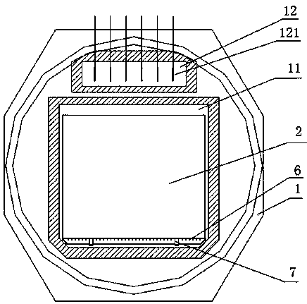
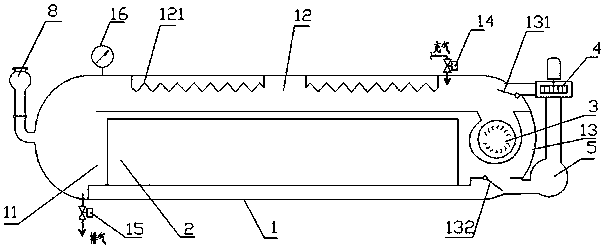
[0027] Such as figure 1 and figure 2 Shown: a hot air circulation brazing furnace, including a furnace body 1, the furnace body 1 is provided with a heating chamber 12 and a working chamber 11, the heating chamber 12 and the working chamber 11 are separate chambers, and the heating chamber 12 and the working chamber The cavities 11 are connected; one side of the furnace body 1 is provided with a main fan 3, through which the gas passing through the heating chamber 12 is introduced into the working chamber 11 to form a hot air circulation channel.

[0028] A resistance heater 121 is arranged in the heating chamber 12 . The gas outlet of the heating chamber 12 is connected with the gas inlet of the workpiece 2, and the gas inlet of the heating chamber 12 is connected with the gas outlet of the workpiece. The furnace body 1 is provided with an inlet valve 14 and an exhaust valve 15 .

[0029] The main fan 3 is a high temperature resistant centrifugal fan. In this embodiment,...

Embodiment 2

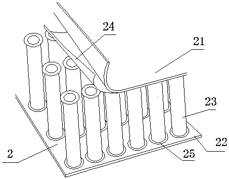
[0037] Such as Figure 4 Shown: The difference from Embodiment 1 is that the workpiece 2' includes a first panel 21', a second panel 22' and a plurality of core plates 23' between them. Core board 23' can be corrugated core board, corrugated core board, rib core board, straight core board etc. The core board 23' of this embodiment is preferably a corrugated core board. A plurality of core plates 23' are arranged at intervals to form a through air channel. Tin solder is provided between the core board 23' and the panel. The hot gas penetrates the inner cavity of the workpiece and contacts with each core plate 23', so that the temperatures of the upper, lower, left, right, front and rear ends of the workpiece are close to each other, and the temperature uniformity is greatly improved.

[0038] Other structures are with embodiment 1.

Embodiment 3

[0040] The difference from Embodiment 1 is that the impeller of the main fan and a part of the motor shaft are arranged in the furnace body, the motor and another part of the motor shaft are arranged outside the furnace body, and the part of the motor shaft extending into the furnace body is wrapped by a water-cooled jacket. The outer side of the water-cooled jacket is provided with an insulating layer.

[0041] Other structures are with embodiment 1.


PUM

PropertyMeasurementUnit
thermal resistanceaaaaaaaaaa

Abstract

The invention provides a hot air circulation brazing furnace. The hot air circulation brazing furnace comprises a furnace body. A heating cavity and a working cavity are formed in the furnace body andcommunicate with each other. A main draught fan is arranged on one side of the furnace body, gas passing through the heating cavity is introduced into the working cavity through the main draught fan,and a hot air circulation channel is formed. The gas is introduced into an inner cavity of a workpiece, and a through gas way is formed in the inner cavity of the workpiece. On one hand, a thermal circulation heating manner is combined with the workpiece with the hollow inner cavity, and the heating time can be shortened; the inner cavity of the workpiece can be directly filled with the hot gas,the temperature differences between all the positions of the workpiece are approximate, the workpiece is more evenly heated, and the brazing quality of the workpiece is greatly improved; the brazing effect is very remarkable; and on the other hand, the hot air circulation brazing furnace can be suitable for brazing, namely the occasions with the brazing atmospheres higher than 450 DEG C.

Description

technical field [0001] The invention relates to the technical field of brazing furnaces, in particular to a hot air circulation brazing furnace. Background technique [0002] When the existing brazing furnace brazes the workpiece, most of them are heated by radiation convection and hot air, and the radiation convection heating method is especially suitable for solid workpieces, that is, only the outer surface of the workpiece is brazed, and the brazing effect significantly. [0003] However, for a workpiece with a hollow cavity, radiant heating will easily lead to uneven and slow heating of the workpiece, resulting in a large temperature difference between the inside and outside of the workpiece. The existing hot air heating method is to carry out hot air circulation on the outer surface of the workpiece, and the hot air blows downward to the workpiece from the upper part, and then blows upward to the workpiece from the lower part, but the brazing will be very slow, and the...

Claims


Application Information

Patent Timeline
Patent Type & Authority Applications(China)
IPC IPC(8): B23K1/008B23K3/04
CPCB23K1/008B23K3/00B23K3/04B23K3/053B23K3/085F04D25/06F04D29/5806F04D29/582F24H3/0405F24H9/1863F24H9/2071F27B9/028F27B9/30F27B9/34F27B2009/305F27D1/0043F27D1/18F27D1/1858F27D1/1866F27D7/02F27D9/00F27D99/0001F27D99/0073F27D2009/0005F27D2009/0037F27D2009/0075F27M2003/05H02K9/19
Inventor 张跃
Owner 张跃
Why Eureka
Try Eureka