Post-mixing abrasive gas jet coal breaking device and coal breaking method thereof

A gas jet and post-mixing technology, applied in liquid/gas jet drilling, earthwork drilling, drilling equipment, etc., can solve the problems of drill pipe system wear, hidden safety hazards of underground workers, and obstruction of coal slag discharge, etc., to improve jet flow Impact force, improve coal breaking effect, and ensure the effect of action effect

Active Publication Date: 2019-03-08
HENAN POLYTECHNIC UNIV
View PDF6 Cites 2 Cited by
  • Summary
  • Abstract
  • Description
  • Claims
  • Application Information

AI Technical Summary

Problems solved by technology

The moisture introduced into the coal seam during the application of this technology will inhibit the gas migration and delay the gas release speed, and in the soft coal seam, holes collapse and blockage often occur, resulting in blockage of gas drainage channels, gas drainage flow and concentration. Extremely low, which seriously limits the popularization and application in soft coal seams
When the abrasive gas jet is used for pressure relief extraction, as for the feeding method, the pre-mixed abrasive jet drilling technology is adopted. Although the abrasive particles accelerate for a long time, the wear on the drill pipe system is serious, and the concentration of the abrasive is difficult to control. Abrasives are easy to accumulate in the front mixing chamber, causing pipeline blockage, seriously affecting the service life of the drill pipe, and it is inconvenient to use and maintain
[0003] In addition, the commonly used gas extraction method in coal mine production is drilling. Installing an air compressor air supply system underground is not only inconvenient to use, but also does not comply with coal mine safety regulations, which poses a safety hazard to underground workers. ; At the same time, there are some problems in the existing drilling method. When the drill bit is drilling, especially in the soft coal seam, it will cause subsidence and hinder the discharge of coal slag. The overall vacuum state is formed, resulting in hole plugging, drilling, etc., and when drilling in a hard coal seam, that is, the Platts coefficient f of the coal seam is greater than 3, it will cause damage to the drill bit, resulting in the drilling process of the drill pipe or drill bit. break in

Method used


Image

  • Post-mixing abrasive gas jet coal breaking device and coal breaking method thereof
  • Post-mixing abrasive gas jet coal breaking device and coal breaking method thereof
  • Post-mixing abrasive gas jet coal breaking device and coal breaking method thereof

Examples


Embodiment 1

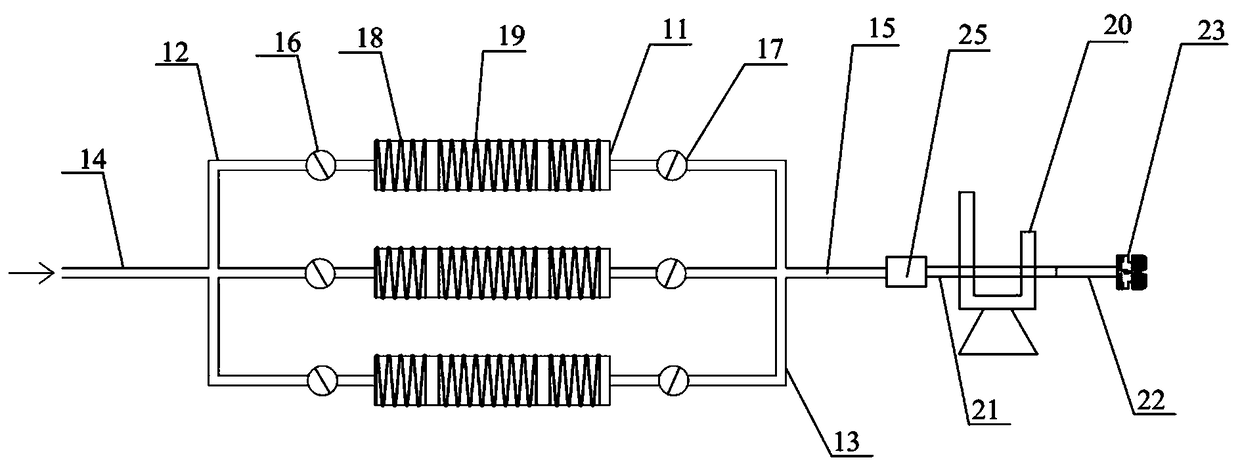
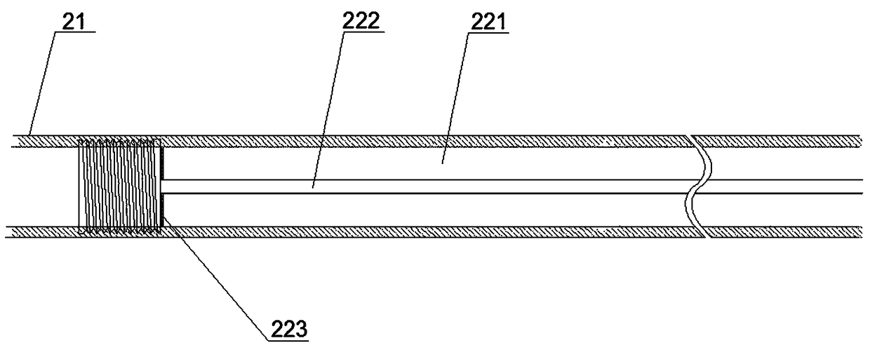
[0063] Embodiment 1: The opening pressure P of the first back pressure valve 235 is set z is 5Mpa, the opening pressure of the second back pressure valve 236 is set to P j 10Mpa, adjust the setting pressure of all the second pressure reducing valves 17 to 5Mpa. At this time, according to the opening characteristics of the back pressure valve, the first back pressure valve 235 is opened, the second back pressure valve 236 is closed, and the axial nozzle 233 Start the auxiliary drilling work. At this time, the drill bit of the drilling rig 20 is in a rotating state. With the advancement of the drill rod 21, the high-pressure abrasive gas jet ejected from the axial nozzle 233 can increase the drilling diameter to achieve the purpose of auxiliary drilling.

Embodiment 2

[0064] Embodiment 2: The opening pressure P of the first back pressure valve 235 is set z is 15Mpa, the opening pressure of the second back pressure valve 236 is set to P j to 8Mpa, adjust the setting pressure of all the second pressure reducing valves 17 to 8Mpa. At this time, the first backpressure valve 235 is closed, the second backpressure valve 236 is opened, and the radial spray nozzle 234 starts to slit. At this time, the drilling rig The drill bit of 20 is in static state, and along with the advancement of drill rod 21, the high-pressure abrasive gas jet flow that radial nozzle 234 sprays cuts out a slit in coal, reaches the purpose of slit.

Embodiment 3

[0065] Embodiment 3: The opening pressure P of the first back pressure valve 235 and the second back pressure valve 236 is set z ,P j are all 8Mpa, adjust the setting pressure of all the second pressure reducing valves 17 to 8Mpa, at this time, the first back pressure valve 235 and the second back pressure valve 236 are all opened, and the axial nozzle 233 and the radial nozzle 234 start simultaneously Work. First start the auxiliary drilling stage, the drill bit of the drilling rig 20 is in a rotating state, and the high-pressure abrasive gas jet ejected from the three-way nozzle is used to increase the diameter of the drilling hole during the advancement of the drill rod 21 to achieve the effect of auxiliary drilling. Then start the slotting stage. At this time, set the drilling machine 20 to a static state and push the rod. In the process of pulling back the rod, use the high-pressure abrasive gas jet ejected from the radial nozzle 234 to slot the coal to achieve the purpo...


PUM


Abstract

The invention discloses a post-mixing abrasive gas jet coal breaking device. The post-mixing abrasive gas jet coal breaking device comprises a drilling assembly and at least two sets of air supply assemblies arranged in parallel, wherein each air supply assembly comprises a tank body, and refrigeration devices are arranged at the two ends of the outer wall of each tank body, and a heating device is arranged in the middle of the outer wall of each tank body; the drilling assembly comprises a drilling machine, and a drill rod inlet of the drilling machine is connected with the high pressure pipeline; a drill rod outlet of the drilling machine is connected with a feeding drill rod, and the feeding drill rod comprises an abrasive pipeline and a gas pipeline arranged in the center inside the abrasive pipeline in a sleeved mode. According to the post-mixing abrasive gas jet coal breaking device, compared with the premixed type abrasive gas jet feeding system, by adopting that abrasive and gas jet are mixed in a mixing cavity, so that the problems of clogging of the pipeline and wearing of a drill rod during down hole application are avoided, and an original drill rod is divided into theabrasive pipeline and the gas pipeline by designing the feeding drill rod, a high-pressure abrasive gas jet is formed by matching with abrasive on the basis of guiding in high-pressure gas, and thus the coal breaking effect is improved.

Description

technical field [0001] The invention relates to the technical field of abrasive gas jets, in particular to a post-mixed abrasive gas jet coal breaking device and a coal breaking method thereof. Background technique [0002] Layout of boreholes for pre-extraction of gas is an important means to prevent and control gas disasters and realize comprehensive utilization of gas energy. The effect requires coal seam pressure relief. Commonly used pressure relief drainage methods mainly include "hydraulic" measures such as high-pressure water jet slotting and hydraulic punching. The moisture introduced into the coal seam during the application of this technology will inhibit the gas migration and delay the gas release speed, and in the soft coal seam, holes collapse and blockage often occur, resulting in blockage of gas drainage channels, gas drainage flow and concentration. It is extremely low, which seriously limits the popularization and application in soft coal seams. When the...

Claims


Application Information

Patent Timeline
Patent Type & Authority Applications(China)
IPC IPC(8): E21B7/18E21B10/61E21B17/00
CPCE21B7/18E21B10/61E21B17/00Y02P70/10
Inventor 刘勇魏建平徐向宇刘笑天张宏图
Owner HENAN POLYTECHNIC UNIV
Why Eureka
Try Eureka