Cross flow type fully-premixed low-NOx boiler

A fully premixed, cross-flow technology, applied to steam boilers, preheating, feed water heaters, etc., can solve problems such as the inability to effectively reduce NOx generation, poor definition of the minimum safe water level, and non-continuous and stable operation of boilers, etc., to achieve Effect of increasing effective heating area, reducing dead zone and interface, and optimizing economizer structure

Pending Publication Date: 2019-03-08
JIANGSU SHUANGLIANG BOILER
View PDF0 Cites 5 Cited by
  • Summary
  • Abstract
  • Description
  • Claims
  • Application Information

AI Technical Summary

Problems solved by technology

②Because the tubes can be arranged freely, the structure is compact, and the boss-type central chamber combustion greatly reduces the volume, but the volume heat load of the boiler furnace is large, and the water is heated to evaporate in one tube, and the cycle rate is low, close to 1, and the water is vaporized and concentrated in the tube, the salt in the water is easy to bind on the tube wall, which can easily lead to heat transfer deterioration, tube burst and fatigue cracks and other faults, so the water quality is high, and the tube wall temperature needs to be strictly controlled within the safe working range Inside
③Because the structure is small, the furnace is small, so the conventional low NO x The burner cannot effectively reduce NO x generation
Because the heat load carried by the economizer is large, and this kind of boiler is often operated in a non-continuous and stable manner, it is easy to vaporize the economizer, so the service life of the economizer is generally short
⑤Because the steam-water interface is in the pipe, the specific position is relatively vague, so it is not easy to define the "minimum safe water level"; at the same time, the upper annular header is relatively small, and the steam dryness is poor, so an external steam-water separation device is required

Method used


Image

  • Cross flow type fully-premixed low-NOx boiler
  • Cross flow type fully-premixed low-NOx boiler
  • Cross flow type fully-premixed low-NOx boiler

Examples


Embodiment Construction

[0025] The present invention will be further described below in conjunction with the accompanying drawings.

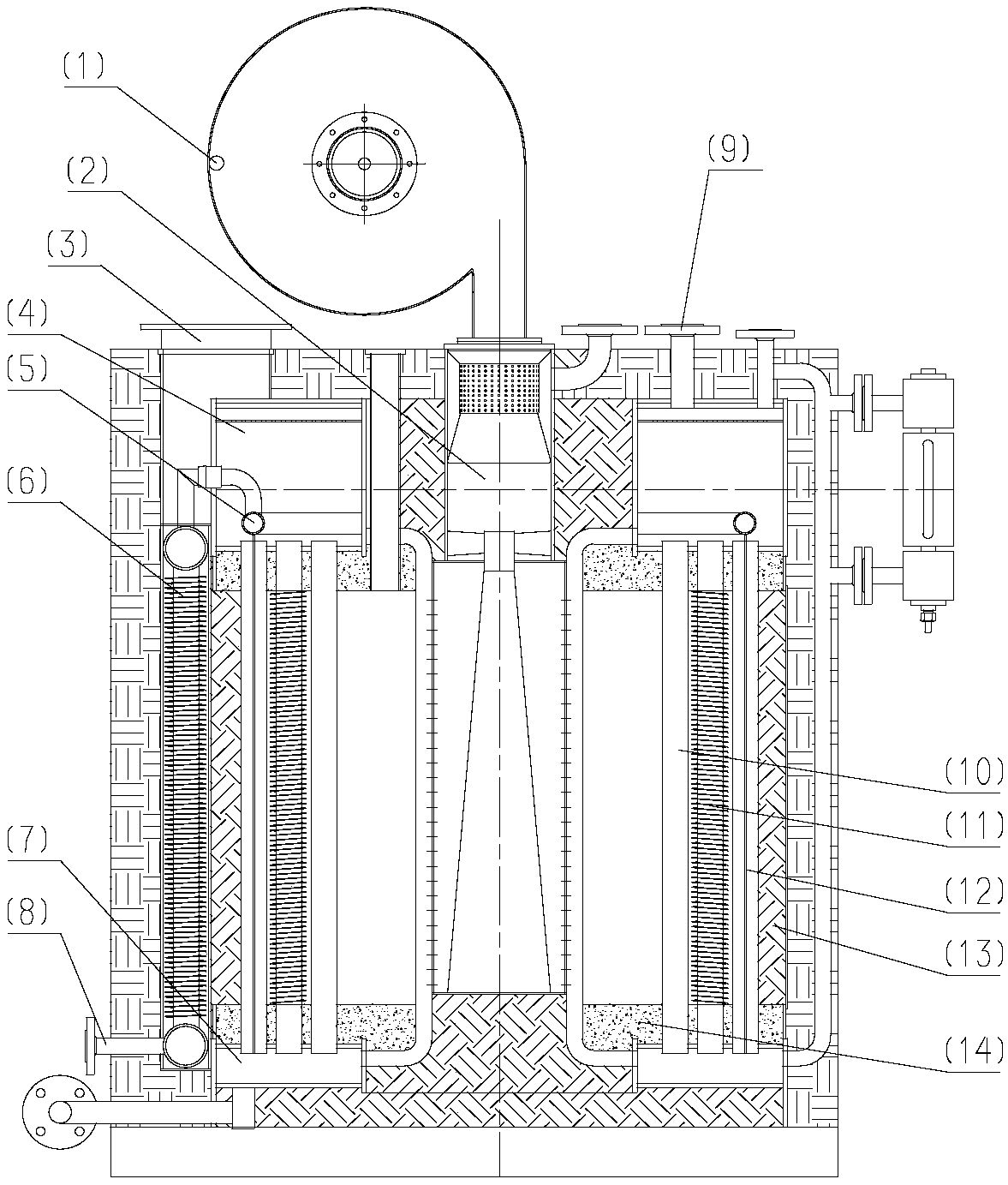
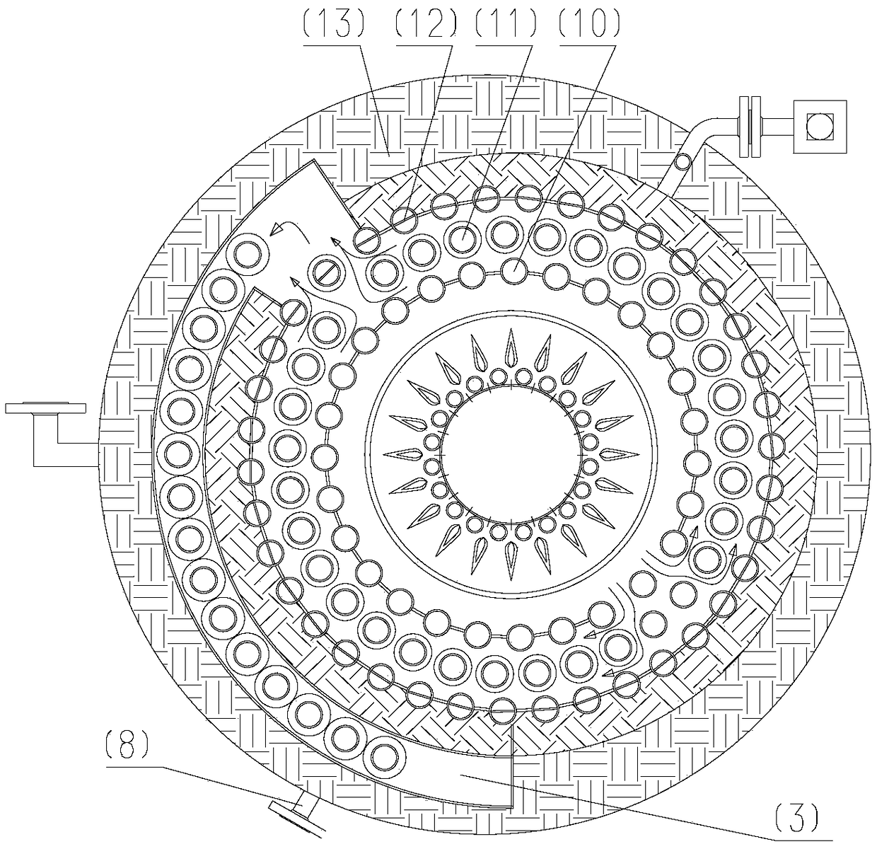
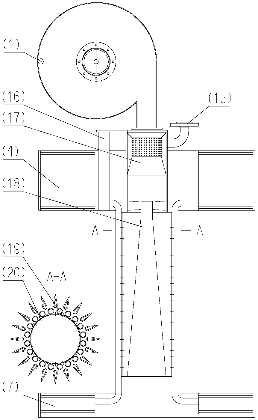
[0026] as attached figure 1 , 2 As shown, a through-flow fully premixed low NO of the present invention x The steam boiler includes fan 1, burner 2, smoke outlet 3, upper annular header 4, water supply circulation device 5, economizer 6, lower annular header 7, water supply port 8, steam outlet 9, inner membrane type Wall pipe 10 , finned pipe 11 in the middle circle, membrane wall pipe 12 in the outer circle, insulation layer 13 and refractory layer 14 . The burner 2 is installed at the inner center of the boiler body, the fan 1 is installed above the burner 2, an upper annular header 4 is arranged at the inner upper part of the boiler body, and an upper annular header 4 is arranged at the inner lower part of the boiler body. A lower annular header 7 is provided, and an inner ring membrane wall tube 10, a middle ring finned tube 11, an outer ring membrane wall tube...


PUM


Abstract

The invention provides a cross flow type fully-premixed low-NOx boiler. The cross flow type fully-premixed low-NOx boiler comprises a draught fan (1), a burner (2), a smoke outlet (3), an upper annular collecting box (4), a feed water circulating device (5), a coal economizer (6), a lower annular collecting box (7), a water feed port (8), a steam outlet (9), inner ring membrane type wall pipes (10), middle ring finned pipes (11), outer ring membrane type wall pipes (12), a heat insulating layer (13) and a fireproof layer (14). Through the structural optimization and integrated design of a body, the burner and the coal economizer, the heating surface is enlarged, the overall structure is more compact, the occupied land is small, the standarization degree is high, and the efficiency is high.The structure of the coal economizer is optimized, and the occupied space of the coal economizer is greatly reduced. Meanwhile, a smoke channel structure of the coal economizer is optimized, and theheat transfer utilization rate of the body and the coal economizer is greatly increased. In addition, the steam-water connection of the coal economizer is optimized, dead zones and connectors are reduced, the possibility of oxygen corrosion is reduced, and the service life of the coal economizer is prolonged.

Description

technical field [0001] The invention belongs to the technical field of gas-fired steam boilers, in particular to a through-flow fully premixed low NO x steamer. Background technique [0002] The once-through boiler originated in Germany, was widely used in Japan, and was introduced into my country in the late 1990s. Due to the compact structure, low steel consumption, small size and fast steam production speed of the boiler, it is especially suitable for hotels, shopping malls, communities and industrial and mining enterprises that need a small amount of steam. Generally, the maximum evaporation capacity does not exceed 4t / h. [0003] The through-flow boiler is composed of long tubes arranged in a designed manner. The feed water pump feeds water at one end of the tube. The water (working medium) passes through the heating water section, the evaporation section, (the superheating section) in the tube, and the required steam is generated from the header on the tube. . It is...

Claims


Application Information

Patent Timeline
IPC IPC(8): F22B31/00F22B37/34F22D1/02
CPCF22B31/00F22B37/34F22D1/02
Inventor 汪新球雷钦祥王殿马文春许清刘建明
Owner JIANGSU SHUANGLIANG BOILER
Why Eureka
Try Eureka