Portable rock-soil mechanics real-time loading test device matched with industrial CT (Computed Tomography) machine

A loading test device and technology of rock and soil mechanics, applied in the direction of measuring device, using stable tension/pressure to test material strength, scientific instruments, etc., can solve the problems of small ray energy, weak X-ray penetration, and crack evolution and development law Difficulties and other problems, to achieve the effect of small loss of ray energy

Pending Publication Date: 2019-03-08
UNIV OF SCI & TECH BEIJING
View PDF8 Cites 14 Cited by
  • Summary
  • Abstract
  • Description
  • Claims
  • Application Information

AI Technical Summary

Problems solved by technology

The traditional CT loading device is mostly placed in the medical CT machine for scanning tests. However, the radiation energy of the medical X-ray CT machine is small (80-140Kev), and it cannot perform fine scanning on large-scale rock and soil samples. There are also great difficulties in the identification of evolution
In addition, traditional medical CT supporting loading equipment mostly uses alloy aluminum materials to make triaxial pressure chambers. Alloy aluminum materials have strong absorption of X-rays. In addition, X-rays used in medical CT have weak penetration and low resolution. As a result, it becomes very difficult to obtain the crack evolution law during the loading process of the sample

Method used


Image

  • Portable rock-soil mechanics real-time loading test device matched with industrial CT (Computed Tomography) machine
  • Portable rock-soil mechanics real-time loading test device matched with industrial CT (Computed Tomography) machine
  • Portable rock-soil mechanics real-time loading test device matched with industrial CT (Computed Tomography) machine

Examples


Embodiment Construction

[0019] In order to make the technical problems, technical solutions and advantages to be solved by the present invention clearer, the following will describe in detail with reference to the drawings and specific embodiments.

[0020] The invention provides a portable rock and soil mechanics real-time loading test device matched with an industrial CT machine.

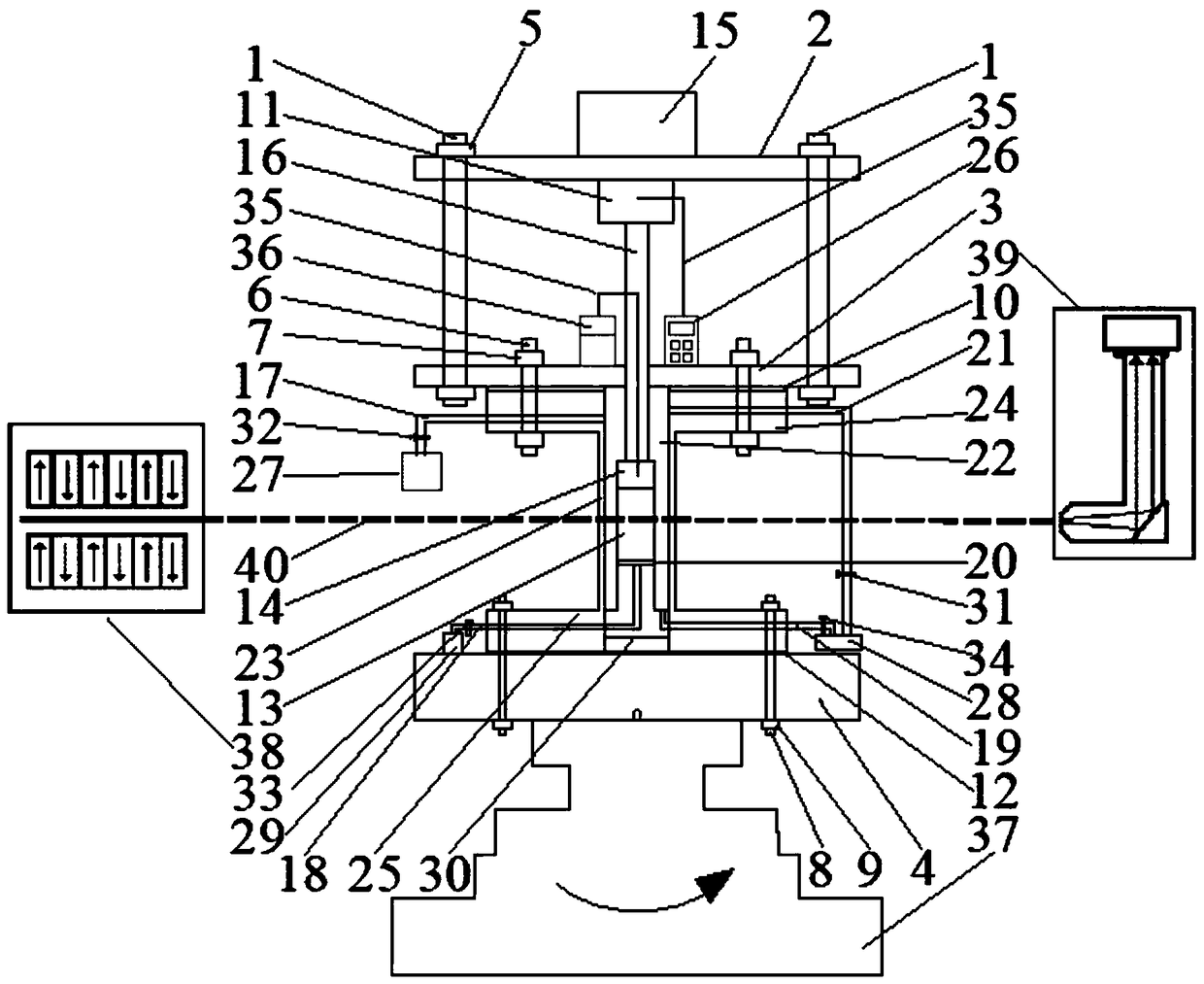
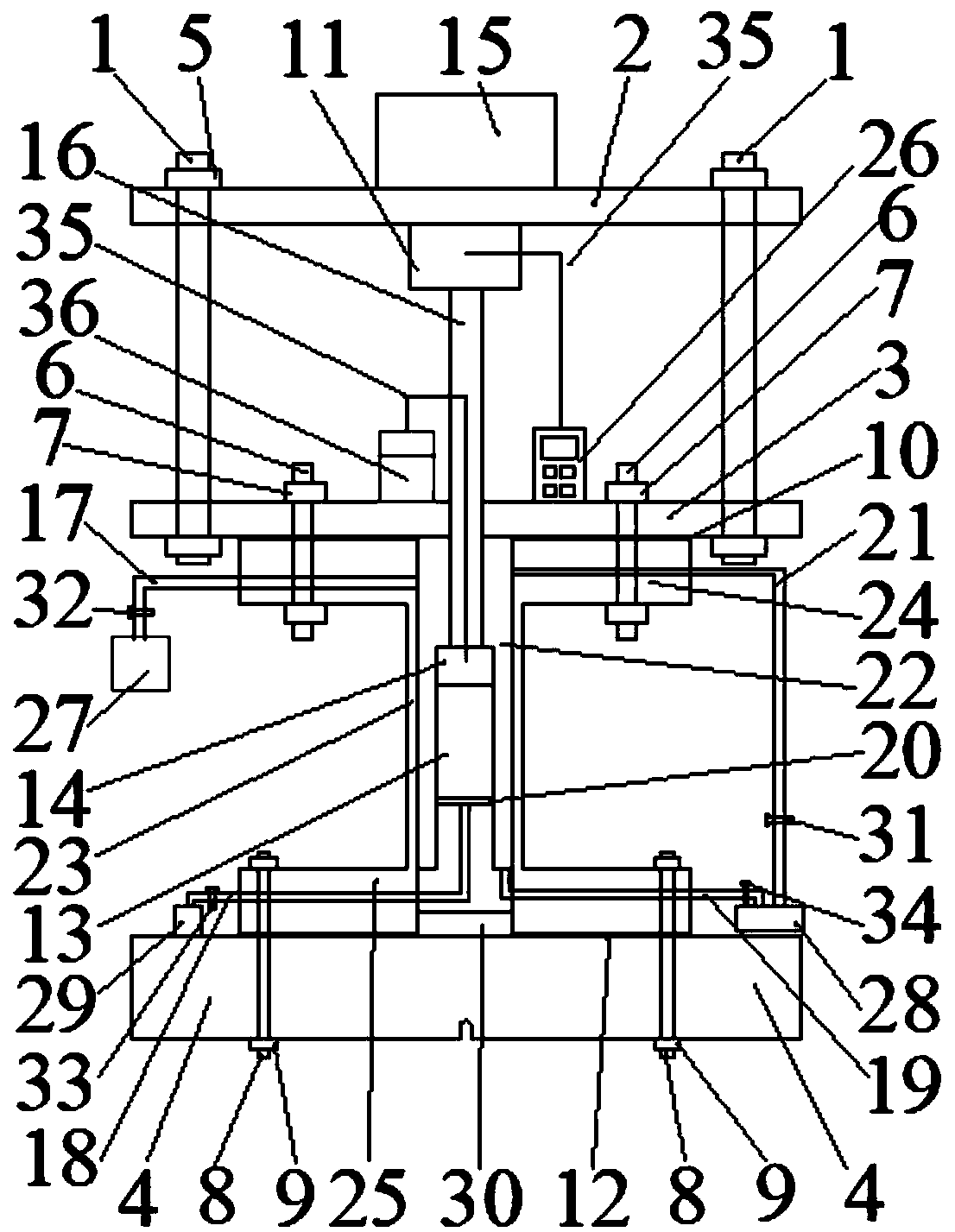
[0021] like figure 2 As shown, the device includes an axial pressure system, a confining pressure system and a physical quantity measurement system,

[0022] The axial pressure system includes a rigid column 1, an upper beam 2, a lower beam 3, a column nut 5, a piston 15, a rigid dowel 16 and a data wire 35, and the rigid column 1, the upper beam 2 and the lower beam 3 are fixed by the column nut 5 , the piston 15 is connected to the rigid dowel 16 via the pressure sensor 11, and the rigid dowel 16 acts on the displacement sensor 14 to pressurize the sample 13;

[0023] The confining pressure system includes a pressur...


PUM

PropertyMeasurementUnit
thicknessaaaaaaaaaa

Abstract

The invention provides a portable rock-soil mechanics real-time loading test device matched with an industrial CT (Computed Tomography) machine, and belongs to the technical field of rock-soil mechanics tests. The portable rock-soil mechanics real-time loading test device comprises an axial pressure system, a confining pressure system and a physical quantity measuring system, wherein the axial pressure system comprises rigid stand columns, an upper cross beam, a lower cross beam, connecting nuts, a piston, a rigid dowel bar and a data lead; the confining pressure system comprises a pressure chamber, a pressurizing production pipe, a sample drain pipe, a pressurizing exhaust pipe, a water-permeable stone, an oil filler pipe, a supercharger, an oil tank, a water storage tank, an oil pipe valve, a pressurizing port valve, a water storage tank valve and an exhaust port valve; and the physical quantity measuring system comprises a pressure sensor, a load controller, a displacement sensor and a data lead. The three systems are arranged on a CT rotary table, and X rays are emitted from a radiation source, penetrate through the barrel wall of the pressure chamber and the sample, are received by a detector, and are transmitted to a computer for reconstruction of a fine sample image. By adopting the device, the problem concerned with visual and digital representation of the internal structural morphology of a rock-soil body sample in a loading deformation process is solved.

Description

technical field [0001] The invention relates to the technical field of rock-soil mechanics test, in particular to a portable rock-soil mechanics real-time loading test device matched with an industrial CT machine. Background technique [0002] Indoor triaxial test is the best way to study the deformation and failure mechanism of rock and soil under the action of stress. Various sensors arranged on the testing machine are used to obtain the stress-strain response reflecting the macroscopic mechanical properties of the sample, but it is impossible to know the inside of the sample. deformation and fracture mechanism. In view of the defects of the triaxial testing machine, the predecessors successively used three methods of electron microscopy, acoustic emission and X-ray CT to apply them to rock and soil testing. However, the scanning electron microscope is obviously affected by the effect of mineral particles, and can only observe the deformation of the sample surface in real...

Claims


Application Information

Patent Timeline
Patent Type & Authority Applications(China)
IPC IPC(8): G01N3/08G01N3/12G01N3/06
CPCG01N3/06G01N3/08G01N3/12G01N2203/0019G01N2203/0641G01N2203/0067
Inventor 王宇李长洪肖永刚侯志强乔趋王华建霍文静
Owner UNIV OF SCI & TECH BEIJING
Why Eureka
Try Eureka