Floatation magnetic separation column device and combined type bubble generator

A technology of bubble generator and magnetic separation column, used in flotation, solid separation and other directions, can solve the problems of complex addition of chemicals, low separation index, and improve concentrate grade, etc., to improve the quality and quantity of production, simple structure, The effect of boosting the effect

Pending Publication Date: 2019-03-12
JIANGSU DAFENG XINANDE MINING CO LTD
View PDF15 Cites 6 Cited by
  • Summary
  • Abstract
  • Description
  • Claims
  • Application Information

AI Technical Summary

Problems solved by technology

Flotation is to use the difference in wettability (hydrophobicity or hydrophilicity) of the surface of various mineral raw material particles to sort water. There are many technical problems in flotation, such as low sorting index, difficult operation and management, and single flotation There are problems such as long process, high cost of flotation, complex addition of reagents, easy fouling of pipelines, and difficulty in filtration.
Magnetic separation uses the difference in magnetic properties of mineral particles to separate magnetic and non-magnetic minerals in an uneven magnetic field. Magnetic separation also has many technical difficulties. Improve the grade of concentrate

Method used


Image

  • Floatation magnetic separation column device and combined type bubble generator
  • Floatation magnetic separation column device and combined type bubble generator
  • Floatation magnetic separation column device and combined type bubble generator

Examples


Embodiment Construction

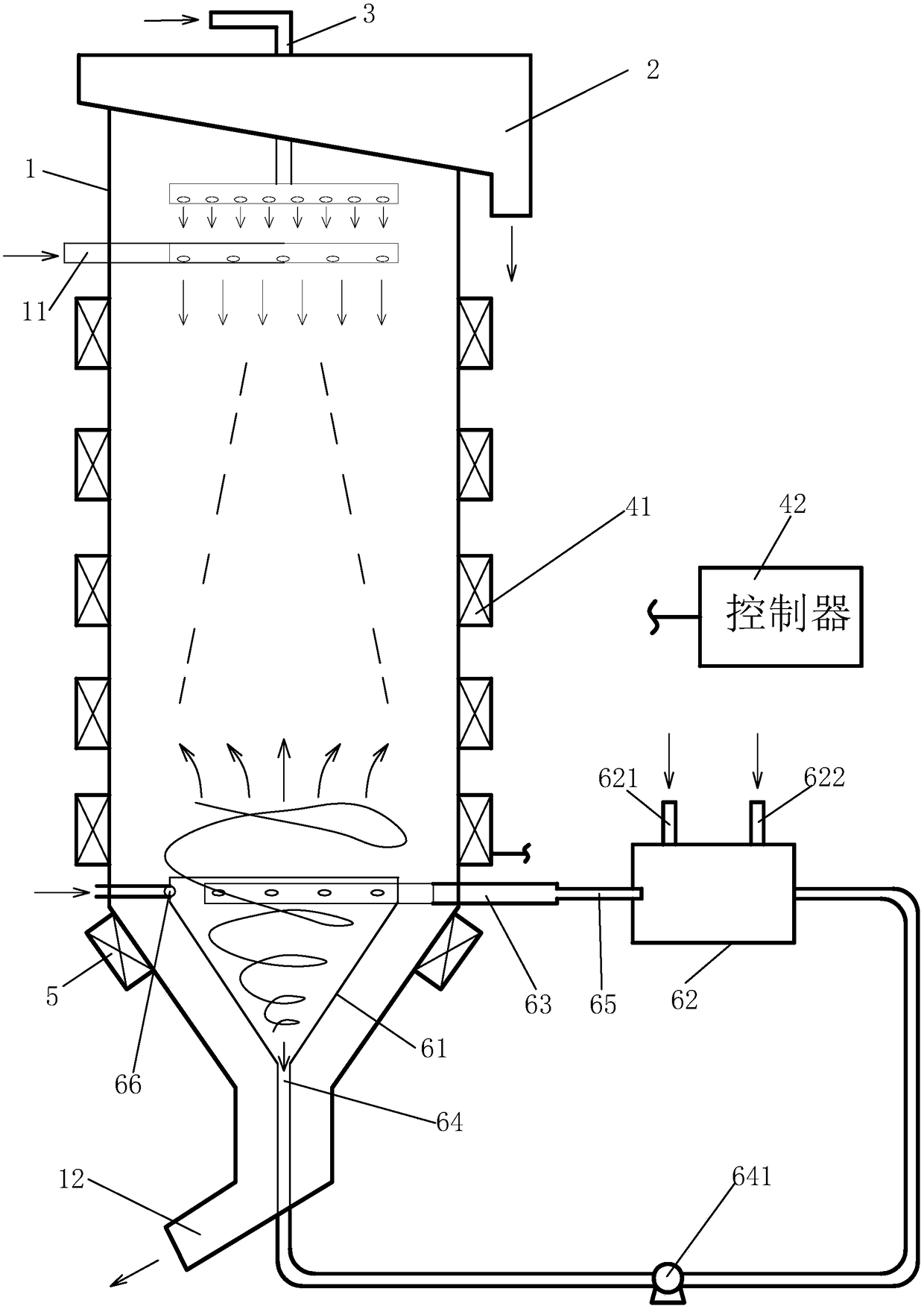
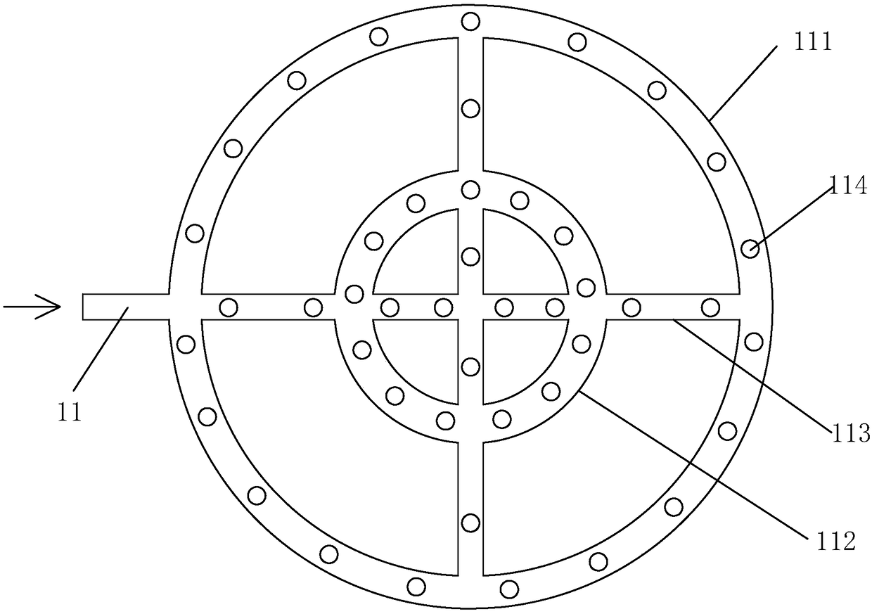
[0036] Such as Figure 1 to Figure 7 As shown, the present invention discloses a floating magnetic column separation device. An overflow tank 2 is arranged on the top of the column barrel 1, a sprinkler 3 is arranged on the upper part of the column barrel 1 and an ore inlet 11 is opened, and the outer inlet of the column barrel 1 is A pulsed magnetic field generator 4 is installed below the mine mouth 11, a demagnetizer 5 is installed outside the column 1 below the pulsed magnetic field generator 4, the diameter of the bottom of the column 1 is gradually reduced to form an iron concentrate outlet 12, and the bottom of the column 1 is installed Combined bubble generator6.

[0037] The combined air bubble generator 6 disclosed by the present invention includes a cone 61 and a suction chamber 62, the cone 61 is sleeved in the column 1, there is a gap between the cone 61 and the column 1, and the top of the cone 61 is The opening is provided for communicating with correspondingly...


PUM


Abstract

The invention discloses a floatation magnetic separation column device. The top of a column casing is provided with an overflow groove. The upper portion inside the column casing is provided with a spray device and an ore inlet. A pulsed magnet field and a demagnetizing device are mounted outside the column casing. The bottom of the column casing is provided with an iron ore concentrate outlet anda combined type bubble generator, wherein the combined type bubble generator comprises a conical barrel and a suction chamber. The conical barrel is arranged in the column casing in a sleeved manner,and a gap is reserved. The top of the column casing is open and communicates with the interior of the column casing. A tangential water pipe and a feeding pipe are arranged at the positions, on the upper portion of the conical barrel, inside the column casing. The bottom of the conical barrel is provided with a discharging pipe which extends out of the bottom of the column casing. The dischargingpipe is provided with a pump. The other end of the discharging pipe is connected to one side of the suction chamber. The suction chamber is provided with a gas inlet and an auxiliary agent addition opening. The other side of the suction chamber is connected with the feeding pipe of the conical barrel through a small-diameter throat pipe. The floatation magnetic separation column device is simplein structure, high in separation index and easy to operate; the grade of concrete can be remarkably raised; and by means of the combined type bubble generator, the generation quality of bubbles can beimproved, and the number of the generated bubbles can be increased; and the floatation treatment effect is improved.

Description

technical field [0001] The invention relates to a floating magnetic column separation device and a combined air bubble generator used therein, belonging to mineral processing equipment. Background technique [0002] Mineral dressing is the most important link in the entire mineral production process, and it is a key department in mining enterprises. Mineral dressing is based on the physical and chemical properties of different minerals in the ore. After the ore is crushed and ground, a suitable method is used to separate the useful minerals from the gangue minerals, and to separate the various symbiotic (associated) useful minerals from each other as much as possible. The process of removing or reducing harmful impurities to obtain raw materials for smelting or other industries. [0003] With the development of science and technology and industry, the requirements for the quality of mineral raw materials are getting higher and higher, and the direct mining of raw ore often ...

Claims


Application Information

Patent Timeline
Patent Type & Authority Applications(China)
IPC IPC(8): B03D1/02B03D1/20B03D103/02
CPCB03D1/02B03D1/1443B03D1/20B03D2203/02
Inventor 唐立靖苏建财苏木清
Owner JIANGSU DAFENG XINANDE MINING CO LTD
Why Eureka
Try Eureka