Eureka AIR delivers breakthrough ideas for toughest innovation challenges, trusted by R&D personnel around the world.

Plant-protection unmanned aerial vehicle

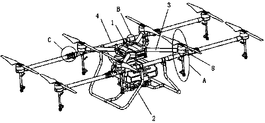
A plant protection UAV and lead-in technology, applied in the field of UAV, can solve the problems of difficulty in meeting the needs of plant protection operations, narrow spraying width, small wheelbase of plant protection UAVs, etc., to save time and cost of plant protection operations, and alleviate High impact force and high spraying efficiency

Pending Publication Date: 2019-03-12
TOPXGUN NAN JING ROBOTICS CO LTD +1
View PDF0 Cites 3 Cited by
  • Summary
  • Abstract
  • Description
  • Claims
  • Application Information

AI Technical Summary

Problems solved by technology

[0003] Existing plant protection drones usually include a fuselage and multiple arms arranged around the fuselage. Plant protection drones are mostly four-axis, one end of the arm is fixedly connected to the fuselage, and a nozzle is installed at the bottom of the other end. , the plant protection UAV with this structure has a small wheelbase, a load of less than 10 kg, and a narrow spray width, which is difficult to meet the needs of current plant protection operations.

Method used


Image

  • Plant-protection unmanned aerial vehicle
  • Plant-protection unmanned aerial vehicle
  • Plant-protection unmanned aerial vehicle

Examples


Embodiment 1

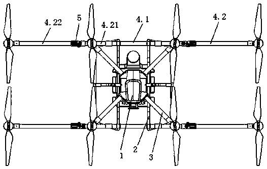
[0037]Existing plant protection drones usually include a fuselage and a plurality of arms arranged around the fuselage. The end of the arm is provided with a rotor assembly, and a spraying device is provided below the rotor assembly. In order to increase the spraying width, usually on the machine Two horizontal bars are connected under the body, the horizontal bar is perpendicular to the center line of the machine head, and the end of the horizontal bar is equipped with a spraying device. The distance between the ends of the two horizontal bars is greater than the original spraying width, so as to achieve the purpose of increasing the spray width The liquid sprayed by the spraying device on the cross bar will be affected by the wind field generated by the rotor assembly on the front and rear arms of the machine, so that the amount of liquid medicine will drift seriously, resulting in uneven spraying, waste of liquid medicine, and affecting the effect of plant protection operatio...

Embodiment 2

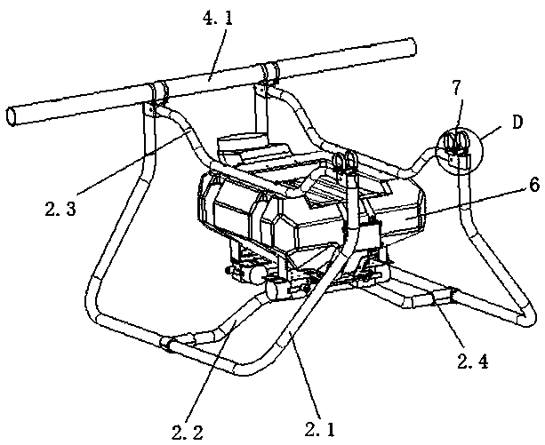
[0044] On the basis of Embodiment 1, in order to improve the stability of the UAV landing, the landing gear 2 provided by this embodiment includes two "U-shaped" brackets 2.1 symmetrically located on both sides of the fuselage and connecting two "U-shaped" brackets. The first connecting frame 2.2 of the "bracket, the two ends of the top of the "U-shaped" bracket are respectively connected to the two long machine arms at the front and rear of the fuselage through the mounting piece 7. The "U-shaped" bracket is used to increase the contact area with the ground, the support is stable, the load-bearing capacity is large, and the impact resistance is high. Compared with other types of landing gear, its structural strength is higher and its service life is longer. Both ends of the first connecting frame 2.2 are respectively connected to the bottoms of the two "U-shaped" brackets 2.1, which is beneficial to enhance the overall strength of the landing gear.

[0045] The side supports ...

Embodiment 3

[0051] On the basis of Embodiments 1 and 2, in order to reduce the space occupied by the plant protection UAV during storage or transportation, the long machine arm is set as a folding machine arm. The existing one-shaped folding machine arm consists of two sections The machine arm, where the two sections of the machine arm meet, one side is rotatably connected, and the other side is fixedly connected by a connecting piece. When the machine arm needs to be folded, the connecting piece is removed, and the two sections of the machine arm are rotated and folded; this kind of folding machine arm , the structure at the fold is not stable and prone to breakage.

[0052] In this embodiment, the segmented arm includes a main arm 4.21 and a support arm 4.22, one end of the main arm 4.21 is connected to the middle arm 4.1, and the other end is connected to the support arm 4.22 through the folding mechanism 5 connect. The folding mechanism includes a first folding part, a second folding...


PUM


Abstract

The invention belongs to the technical field of unmanned aerial vehicles, and particularly relates to a plant-protection unmanned aerial vehicle. The plant-protection unmanned aerial vehicle comprisesa machine body, an undercarriage, short machine arms and long machine arms, wherein the multiple short machine arms are arranged around the machine body, the two long machine arms are mutually parallel and are arranged on the front side and the back side of the machine body respectively, one ends of the short machine arms are fixedly connected on the machine body, and the other ends of the shortmachine arms are provided with first rotor wing assemblies and fixedly connected with the long machine arms; second rotor wing assemblies are arranged at the two ends of the long machine arms respectively, and sprinkling devices are arranged at the bottoms of all the rotor wing assemblies; a top support of the undercarriage is connected to the bottoms of the long machine arms. According to the plant-protection unmanned aerial vehicle, the whole structural arrangement is reasonable, multi-rotor-wing abnormal-shape arrangement is adopted, a load is large, and the whole strength of the machine body structure is guaranteed under the condition that the sprinkling width is increased; compared with a traditional multi-rotor-wing unmanned aerial vehicle, the sprinkling width is large under the equivalent load condition, the sprinkling efficiency is high, plant-protection operation time can be shortened, and the cost can be saved.

Description

technical field [0001] The invention relates to the technical field of drones, in particular to a plant protection drone. Background technique [0002] A drone is an unmanned aerial vehicle operated by a radio remote control device or its own program control device. With the rapid development of the drone industry, more and more drones are being applied to industries such as agriculture, forestry, electric power, surveying and mapping, and telemetry. With the maturity of drone technology and the popularization of modern agricultural concepts, the application of plant protection drones is becoming more and more extensive. The use of plant protection drones to spray pesticides can not only save manpower and material resources, but also keep away from remote control operations and avoid spraying operations. Personnel are exposed to pesticides, which improves the safety and spraying efficiency of pesticide spraying operations. [0003] Existing plant protection drones usually ...

Claims


Application Information

Patent Timeline
Patent Type & Authority Applications(China)
IPC IPC(8): B64D1/18B64C27/08B64C1/06B64C1/30
CPCB64C1/06B64C1/069B64C1/30B64C27/08B64D1/18
Inventor 高廉洁尹亮亮张羽
Owner TOPXGUN NAN JING ROBOTICS CO LTD
Why Eureka
Eureka Blog
Learn More