Automatic cleaning optical flow cell

A technology of automatic cleaning and flow cell, which is applied in the direction of material analysis, scientific instruments, and measuring devices through optical means. It can solve problems such as easy generation of air bubbles, inability of motors to resist corrosion and high temperature, and drift of measurement baselines. It achieves simple structure and design. ingenious effect

Pending Publication Date: 2019-03-12
广州泰格测控技术有限公司
View PDF0 Cites 2 Cited by
  • Summary
  • Abstract
  • Description
  • Claims
  • Application Information

AI Technical Summary

Problems solved by technology

[0002] For a long time, there has not been a very good way to clean the pollutants on the inner wall of the container, especially for optical analysis instruments and continuous online analysis instruments through testing transmittance
In the existing technology, the commonly used cleaning methods include: motor-driven mechanical brush cleaning, vibration cleaning, jet cleaning, pharmacological cleaning, ultrasonic cleaning, etc., but for the quartz glass tube optical flow cell commonly used in optical analysis instruments , the commonly used liquid cleaning method has the following deficiencies: ①, motor-driven mechanical brush cleaning, the structure is more complex and prone to mechanical failures, if the object in contact with the glass is strong, it is easy to affect the transmittance library and thus affect the measurement results, and because of the cleaning part It is not easy to seal with the glass part. When cleaning, you can only stop the measurement work, and it is more complicated to restore the working state after cleaning; it is also easy to generate air bubbles, and the motor cannot be anti-corrosion and high-temperature resistant; ② Vibration cleaning and glass inner wall cleaning are indirect, except for the outlet In addition to the large power drive, it will also affect the sealing part, and even damage the glass tube due to strong vibration. If the measurement part cannot be restored, it will affect the measurement baseline drift and it is not easy to clean, which will eventually affect the measurement result; ③. Jet cleaning, because the cleaning state is related to the pressure, so when the pressure is low, the cleaning effect cannot be achieved at all. If the pressure is too high, it may sometimes exceed the storage capacity of the glass and sealing materials. Due to the complexity of fluid mechanics, the viscosity of the liquid It will directly affect the cleaning effect and the turbulent flow will also affect the measurement results. If the sample contains water and the amount of impurities is large, it will also block the jet hole. Due to the special structure of the jet technology, it is not easy to design successfully, and the cleaning effect is not very good; ④Pharmaceutical cleaning, It means that the measurement system stops detection, and injects chemicals such as methanol, ethanol, acetone, toluene, acid and alkaline liquids and special cleaning liquids into the contaminated glass tube. At this time, the measurement system must stop working and perform more complicated operations before cleaning The liquid is poured into the glass container and needs to be soaked and diluted, and then it can be cleaned by stirring and rubbing with a brush and related objects. In addition to affecting continuous measurement, this system operation also has the following disadvantages: the cleaning liquid is not easy to clean, Some measured liquids related to chemical reactions are not allowed at all. If the glass container is removed, it is difficult to restore the position and affect the measurement standard. Sometimes the detection system has to be re-calibrated. Large samples cannot adapt to it at all; ⑤ultrasonic cleaning is to use the ultrasonic element to be closely combined with the glass container. After the ultrasonic generator is started, the glass container also vibrates in the ultrasonic frequency band, and the pollutants on the inner wall of the glass are cleaned by high-speed ultrasonic vibration. Ultrasonic elements and glass can be realized as a whole in structure, so the original flow path structure will not be damaged during cleaning, but the high ultrasonic drive power does not have a good cleaning effect for viscous liquids, and for continuous flowing liquids, when the temperature is higher than At 70°C, the ultrasonic generating element, that is, the piezoelectric ceramic, may fail to perform the cleaning function. Furthermore, due to the strong ultrasonic electromagnetic radiation, it is easy to interfere with the measuring sensor. Practice has proved that the effect of ultrasonic cleaning is not obvious.

Method used


Image

  • Automatic cleaning optical flow cell
  • Automatic cleaning optical flow cell
  • Automatic cleaning optical flow cell

Examples


Embodiment

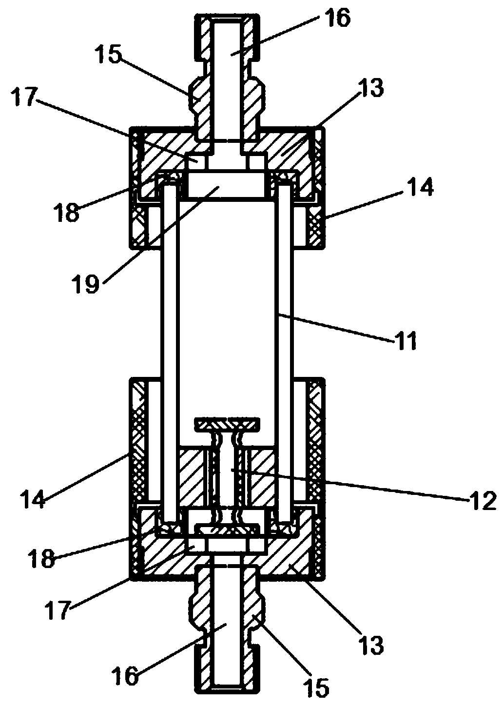
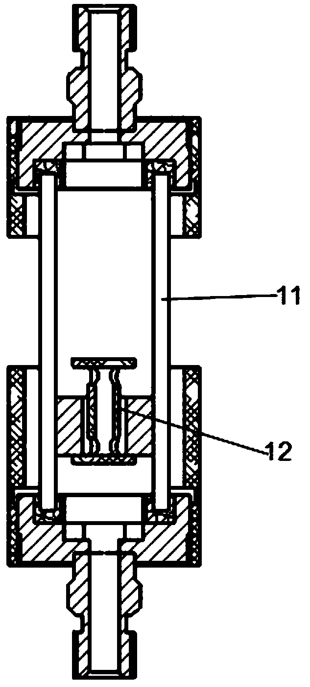
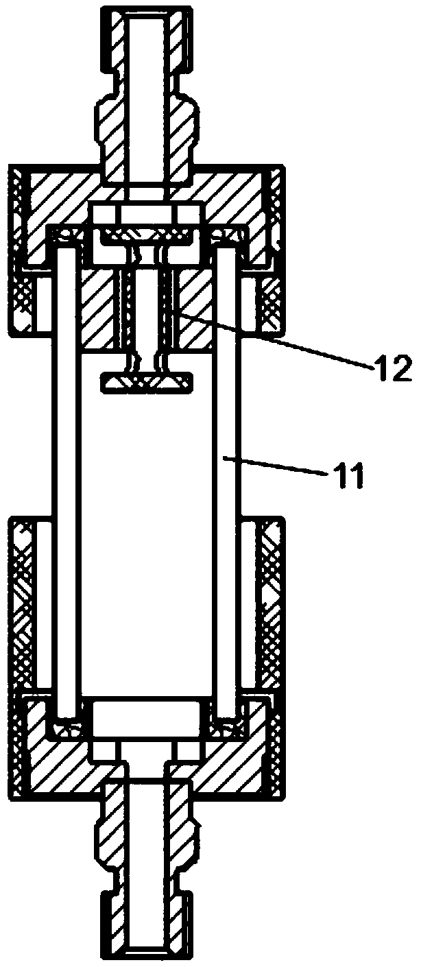
[0020] Embodiment: an automatic cleaning optical flow cell.

[0021] refer to Figure 1 to Figure 7As shown, an automatic cleaning optical flow cell includes a flow cell body 1, a first three-way solenoid valve 2, a second three-way solenoid valve 3, a controller 4, an optical sensor 5 and a light source 6, wherein the light source 6 and the optical sensor 5 are symmetrically installed on the left and right sides of the flow cell body 1, the first three-way solenoid valve 2 and the second three-way solenoid valve 3 are respectively connected to the flow cell body 1 through pipelines, the first three-way solenoid valve 2, the second three-way solenoid valve The three-way solenoid valve 3, the optical sensor 5 and the light source 6 are all electrically connected to the controller 4. In the actual detection process, the function of the light source is to provide the required light for optical detection, and input the detected data through the optical sensor 5. Store and output ...


PUM


Abstract

The invention provides an automatic cleaning optical flow cell. The automatic cleaning optical flow cell comprises a quartz glass tube, end covers installed on the upper end and lower end of the quartz glass tube, installation connectors welded on the top of the end covers, blind plate limiting retainer rings, and a cleaning assembly installed in the quartz glass tube, wherein a concave piston limiting washer is installed on a contact position between the inner wall of the end cover and the quartz glass tube; the blind plate limiting retainer rings are installed in the end covers and disposedon the bottom of a flow cavity, and the inner side wall of the blind plate limiting retainer ring is provided with a through hole communicated with the flow cavity; the cleaning assembly comprises a cleaning piston, a casing pipe and a moving pipe, the upper end and the lower end of the moving pipe are respectively provided with a blind plate, the side wall of junctions between the upper end and lower end of the moving pipe and the blind plates are respectively provided with a guide hole, the casing pipe sleeves the outer side of the moving pipe, the cleaning piston is fixed on the outer sideof the casing pipe, and the outer wall of the cleaning piston is closely fit to the inner wall of the quartz glass tube. The automatic cleaning optical flow cell is simple in structure and ingenious in design, and utilizes the pressure of the liquid to automatically online complete the cleaning work for the inner side of a pipe wall.

Description

technical field [0001] The invention relates to the technical field of optical analysis instruments, in particular to an automatic cleaning optical flow cell. Background technique [0002] For a long time, there has been no very good way to clean the pollutants on the inner wall of the container, especially for optical analysis instruments and continuous online analysis instruments through testing transmittance. In the existing technology, the commonly used cleaning methods include: motor-driven mechanical brush cleaning, vibration cleaning, jet cleaning, pharmacological cleaning, ultrasonic cleaning, etc., but for the quartz glass tube optical flow cell commonly used in optical analysis instruments , the commonly used liquid cleaning method has the following deficiencies: ①, motor-driven mechanical brush cleaning, the structure is more complex and prone to mechanical failures, if the object in contact with the glass is strong, it is easy to affect the transmittance library ...

Claims


Application Information

Patent Timeline
IPC IPC(8): G01N21/05G01N21/15
CPCG01N21/05G01N21/15G01N2021/152
Inventor 简宏潘明虎车简铭黄鸣谢宇宙黄鹤张旭辉
Owner 广州泰格测控技术有限公司
Why Eureka
Try Eureka