
Three-phase switched reluctance motor sensorless control method and device based on line inductance feature point extraction

A feature point extraction, three-phase switching technology, applied in electronic commutation motor control, motor control, AC motor control and other directions, can solve problems such as low flexibility and real-time performance, large system resources, and complex algorithms

Active Publication Date: 2019-03-12
HUNAN UNIV OF SCI & TECH
View PDF3 Cites 1 Cited by
  • Summary
  • Abstract
  • Description
  • Claims
  • Application Information

AI Technical Summary

Problems solved by technology

Among them, the inductance model method is to store the inductance, current and corresponding rotor position of the motor in a three-dimensional table in advance. When the motor is running, it only needs to collect the current value in real time and perform simple calculation processing, and then obtain the corresponding value according to the data table. Rotor position angle; the algorithm of this method is simple, but it takes up a lot of system resources, and the flexibility and real-time performance are not high
The intelligent control method is to establish a nonlinear mapping model with current and flux linkage as input and rotor position angle as output, and then estimate the rotor position angle by collecting current and flux linkage values ​​in real time according to the model; this method position estimation High precision, but there are disadvantages such as complex algorithm, heavy calculation workload, and low real-time performance
The flux linkage / current law is to apply chopper control current to the conduction phase of the switched reluctance motor and apply high-frequency detection pulses to the non-conduction phase, and then use the position angle of the inductance intersection of the conduction phase and the non-conduction phase to measure the motor The rotor position is estimated; this algorithm has the advantages of less system resources and moderate computing workload, but when the conduction phase current is greater than its critical saturation current, the position of the above-mentioned phase inductance intersection point will change with the increase of conduction phase current Offset, resulting in a large deviation when estimating the motor rotor position, thus seriously affecting the improvement of motor control accuracy

Method used


Image

  • Three-phase switched reluctance motor sensorless control method and device based on line inductance feature point extraction
  • Three-phase switched reluctance motor sensorless control method and device based on line inductance feature point extraction
  • Three-phase switched reluctance motor sensorless control method and device based on line inductance feature point extraction

Examples


Embodiment 1

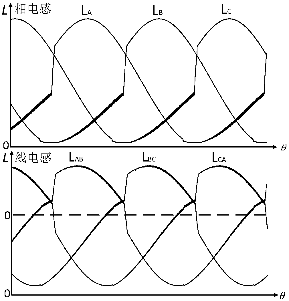
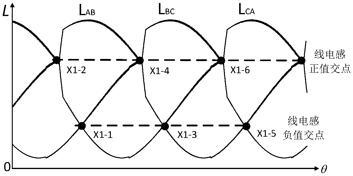
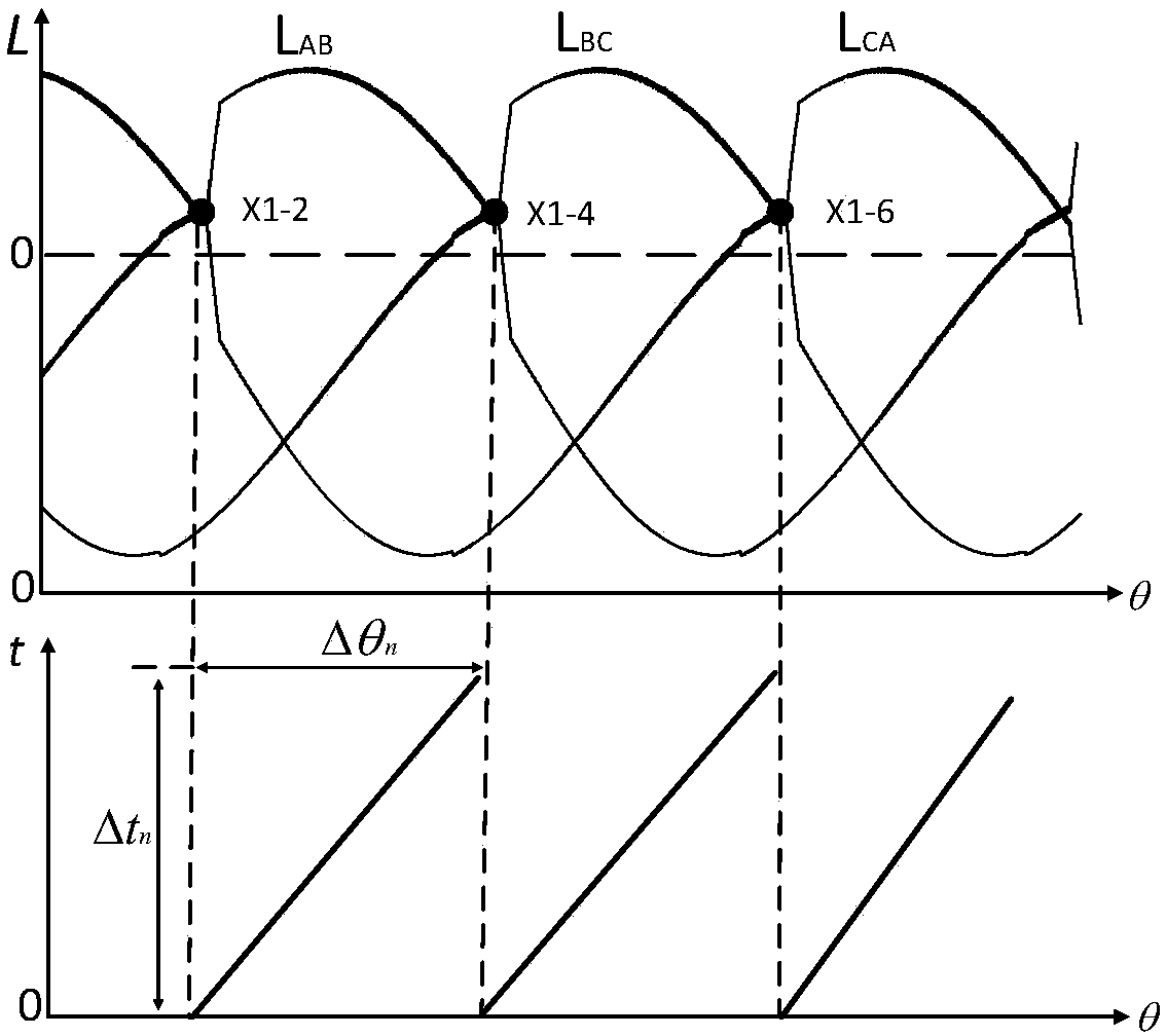
[0057] figure 1 It is a graph of the phase inductance and line inductance of the three-phase switched reluctance motor of the present invention. figure 1 The upper middle is the phase inductance curve, and the lower one is the line inductance curve. In the phase inductance curve, the first conduction phase of the motor in the rotor cycle is the A phase, the subsequent conduction phase is the B phase, and the last conduction phase is the C phase. According to the real-time detection of the current peak value and the bus voltage value of each phase winding, the inductance value of each phase winding is calculated from the formula (1), and the function relationship is obtained from a series of inductance values ​​of each phase winding using the numerical fitting method, as follows: Formula (2) ~ formula (4) shown.

[0058]

[0059] L A (θ)=K 1 sin(θ)-K 2 sin(2θ)+K 3 (2)

[0060] L B (θ)=K 1 sin(θ-2π / 3)-K 2 sin(2θ+2π / 3)+K 3 (3)

[0061] L C (θ)=K 1 sin(θ+2π...

Embodiment 2

[0079] Figure 4 It is a structural block diagram of a three-phase switched reluctance motor position sensorless control device based on line inductance feature point extraction in the present invention. The control device includes a microcontroller, a power conversion circuit drive module, a power conversion circuit, a current detection module, and a voltage detection module. modules, input and output modules, and DC stabilized power supplies. The microcontroller is respectively connected to the power conversion circuit drive module, the current detection module, the voltage detection module and the input and output module; the power conversion circuit is respectively connected to the power conversion circuit drive module, the current detection module and the voltage detection module; wherein:

[0080] The microcontroller is used to send a control signal to the power conversion circuit through the power conversion circuit drive module, and output the chopping control current ...


PUM


Abstract

The invention discloses a three-phase switched reluctance motor sensorless control method and device based on line inductance feature point extraction. The control method comprises the steps that three phase line inductance function relations are obtained through real-time phase inductance values of three phase windings of a three-phase switched reluctance motor, and then feature points of three phase line inductances are determined; and the rotor position angle of a motor rotor at any moment in a next corresponding interval is calculated according to the average rotating speed in a corresponding interval of two adjacent line inductance feature points, and a corresponding signal is output to achieve precise sensorless control over the three-phase switched reluctance motor. A control devicecomprises a microcontroller, a power conversion circuit driving module, a power conversion circuit, a current detection module, a voltage detection module, an input and output module and a direct current stabilized power supply. Compared with the prior art, the three-phase switched reluctance motor sensorless control method and device have the advantages that influences of magnetic circuit saturation on the rotor position estimation precision are effectively avoided, and an algorithm is simple.

Description

technical field [0001] The invention relates to the field of switched reluctance motor control, in particular to a position sensorless control method and device for a three-phase switched reluctance motor based on line inductance feature point extraction. Background technique [0002] The switched reluctance motor has a series of advantages such as small starting current, large starting torque, high efficiency, simple and solid structure, strong fault tolerance, wide speed range, etc., and has been widely used in many fields such as electric vehicles, aviation industry, and mining. application. In order to realize the high-performance control of the switched reluctance motor, it is necessary to obtain the position information of the motor rotor accurately and in real time. Traditionally, the position sensor is mainly used to obtain the position information of the motor rotor, but the introduction of the position sensor not only increases the cost and complexity of the speed...

Claims


Application Information

Patent Timeline
Patent Type & Authority Applications(China)
IPC IPC(8): H02P6/185
CPCH02P6/185H02P2207/05H02P25/089
Inventor 张小平匡斯建刘苹张铸姜海鹏周少武
Owner HUNAN UNIV OF SCI & TECH
Learn More