
Machining device for material for diamond grinding wheel

A technology of diamond grinding wheel and processing equipment, applied in the field of diamond grinding wheel, can solve the problems of low heating efficiency, low processing efficiency, high energy consumption, etc., and achieve the effects of improving performance, saving materials and reducing production costs

Inactive Publication Date: 2019-03-15
LIUZHOU KAITONG NEW MATERIAL TECH CO LTD
View PDF1 Cites 2 Cited by
  • Summary
  • Abstract
  • Description
  • Claims
  • Application Information

AI Technical Summary

Problems solved by technology

[0003] At present, most of the artificially synthesized diamonds are in the form of powder or fine particles. In order to use diamonds for high-precision and high-efficiency grinding, bonding agents are usually used to bond diamond abrasive grains and make them with a certain strength and Shaped mold, so that it is easy to be installed on various grinding machines for grinding processing, but due to the limitation of processing equipment, the existing steel grinding wheel materials lead to low processing efficiency and poor performance. To this end, Chinese patent CN 107671751 A proposes A processing equipment for materials used in diamond grinding wheels. The equipment has the advantages of improving processing efficiency and performance. However, when the device is in use, due to the adhesiveness of titanium dioxide sol, it will adhere to the filter plate and affect the use, resulting in titanium dioxide. Waste of sol; the heating device heats through thermal radiation, which consumes a lot of energy and has low heating efficiency

Method used


Image

  • Machining device for material for diamond grinding wheel
  • Machining device for material for diamond grinding wheel
  • Machining device for material for diamond grinding wheel

Examples


Embodiment Construction

[0022] The following will clearly and completely describe the technical solutions in the embodiments of the present invention with reference to the accompanying drawings in the embodiments of the present invention. Obviously, the described embodiments are only some, not all, embodiments of the present invention.

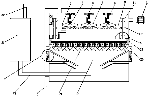
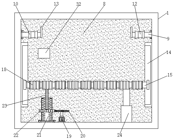
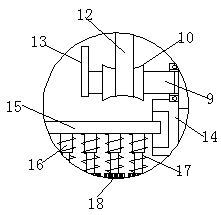
[0023] refer to Figure 1-4, a processing equipment for diamond grinding wheel materials, comprising a casing 1, a working motor 2 is fixedly connected to the right side of the casing 1, a rotating shaft 3 is fixedly connected to the output end of the working motor 2, and a surface of the casing 1 is fixedly connected There is a motor base, the upper surface of the motor base is fixedly connected with the working motor 2, the left end of the rotating shaft 3 runs through and extends to the inside of the casing 1, and the left side wall of the inside of the casing 1 is connected to the rotating shaft 3 through a bearing in rotation, and the rotating shaft 3 The outer ...


PUM


Abstract

The invention discloses a machining device for a material for a diamond grinding wheel. A machine shell is included, and the right side face of the machine shell is fixedly connected with a work motor; the output end of the work motor is fixedly connected with rotating shafts, and the outer surfaces of the rotating shafts are fixedly connected with a group of driving conical gears; a group of vertical rods are rotationally connected to the top wall in the machine shell through bearings; and the outer surfaces of the vertical rods are fixedly connected with driven conical gears. According to the machining device for the material for the diamond grinding wheel, by arranging the work motor, the work motor drives the rotating shafts to rotate, and the rotating shafts drive two supporting rodsto rotate through a first coil, a second coil and two connection belts; the two supporting rods drive eccentric wheels to rotate; when the eccentric wheels are connected with a filtering plate, the filtering plate moves downwards; when the eccentric wheels are connected with the filtering plate, the filtering plate moves upwards under the effect of a vibrating spring, and an up-down vibrating effect is achieved; and redundant titanium dioxide sol is vibrated to fall, and therefore the effects of saving the material and lowering the production cost are achieved.

Description

technical field [0001] The invention relates to the technical field of diamond grinding wheels, in particular to a processing equipment for materials used in diamond grinding wheels. Background technique [0002] Diamond grinding wheels are different from ordinary abrasive grinding wheels in structure. Generally, they are composed of diamond abrasive layer, transition layer and matrix. The working layer, also known as diamond layer, is composed of abrasive, bonding agent and filler. It is the working part of the grinding wheel. The non-diamond layer, also known as the non-diamond layer, is composed of binder, metal powder and filler. It is the part that firmly connects the diamond layer to the substrate. The substrate is used to accept the abrasive layer and is firmly clamped on the grinding machine with a flange during use On the main shaft, steel and alloy steel powder are generally used as substrates for metal bond products, and aluminum alloy and bakelite are used as sub...

Claims


Application Information

Patent Timeline
IPC IPC(8): B24D18/00
CPCB24D18/0063
Inventor 黎超英吴沛荣
Owner LIUZHOU KAITONG NEW MATERIAL TECH CO LTD
Learn More