Experimental facility capable of implementing visualization of condensation of inside and outside of steam tube

An experimental device and steam tube technology, which is applied in the field of condensation heat transfer experiments, can solve the problems of inability to conduct condensation experiments in the tube and inability to conduct condensation experiments outside the tube.

Active Publication Date: 2019-03-15
ZHEJIANG UNIV
View PDF10 Cites 3 Cited by
  • Summary
  • Abstract
  • Description
  • Claims
  • Application Information

AI Technical Summary

Problems solved by technology

Among the published patents, the "Integrated Experimental Device for Evaporation and Condensation in a Single Tube" disclosed in the patent document No. 200820155479.6 can only conduct evaporation and condensation experiments in the tube, but cannot conduct condensation experiments outside the tube; the patent application number is 201220144021.7 patent document disclosed "single-tube external evaporation and condensation heat transfer performance test device" can only conduct external evaporation and condensation experiments, can not conduct in-tube condensation experiments; patent application number 201210540382. The steam condensation heat transfer experimental device for multi-component non-condensable gases" and the "condensation heat transfer experimental device that can realize the coupling of natural circulation and forced circulation" disclosed in the patent application number 201310084890.4 can only be used for condensation outside the steam pipe. The process is tested, and the condensation outside the vertical tube is carried out

Method used


Image

  • Experimental facility capable of implementing visualization of condensation of inside and outside of steam tube
  • Experimental facility capable of implementing visualization of condensation of inside and outside of steam tube
  • Experimental facility capable of implementing visualization of condensation of inside and outside of steam tube

Examples


Embodiment Construction

[0024] Below in conjunction with accompanying drawing, the present invention is described in further detail:

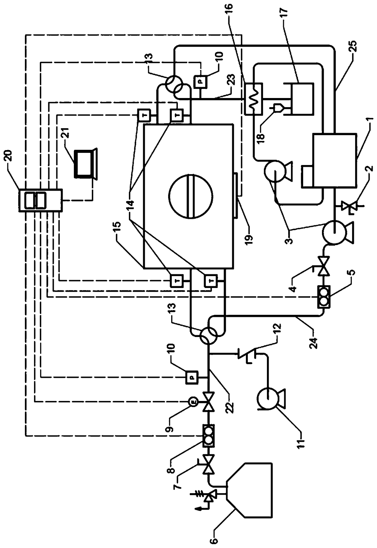
[0025] It mainly includes steam supply system, cooling water system, vacuum system, visual experiment body and data acquisition system.

[0026] In the steam supply system, the steam generator 6 generates steam, the initial steam flow is controlled by the steam flow regulating valve 7, and the vortex flowmeter 8 records the cumulative flow and the instantaneous flow. An electric valve 9 is installed on the gas supply main pipe, which can adjust its opening according to the negative feedback of the set condensing pressure to control the steam flow. When carrying out the in-pipe condensation experiment, switch the two four-way valves 13 so that the main air supply pipe 22 and the main exhaust pipe 23 are connected to the experimental pipe section 30 , and the main water supply pipe 24 and the main return water pipe 25 are connected to the vacuum cavity 15 . When carryi...


PUM


Abstract

The invention discloses an experimental facility capable of implementing visualization of condensation of the inside and outside of a steam tube. The experimental facility mainly comprises a steam supply system, a cooling water system, a vacuum system, a visualization experimental body and a data acquiring system. A gas supply main tube is connected with a vacuum cavity or an experimental tube section through a four-way valve, and an exhaust main tube is arranged at the rear of the cavity, and is connected with an aftercooler and a condensation tank. The aftercooler provides a cold source fromconstant-temperature water bath. A cooling water branch line enters the experimental tube section or the vacuum cavity via a flowmeter under the effect of a water pump, after heat exchange, the cooling water branch line returns to the constant-temperature water bath from a water return main tube, and the other branch line enters a tube side of the aftercooler under the effect of the water pump, and then returns to the constant-temperature water bath after heat exchange. Before an experiment, a high vacuum environment in the vacuum cavity or the experimental tube section is realized by the vacuum system. By cooperation of a front four-way valve and a rear four-way valve of the vacuum cavity, condensation of the inside of the tube or condensation of the outside of the tube can be continuously measured and analyzed and visually detected by the device under different steam pressures, different degrees of supercooling and different surface structural characteristics.

Description

technical field [0001] The invention relates to an experimental device capable of realizing condensation visualization inside and outside a steam pipe, and belongs to the field of condensation heat exchange experiments. Background technique [0002] Steam condensation is a very common phenomenon in nature and industrial applications. Among them, the most common is the condensation of pure water vapor. Condensation of water vapor is a basic form of heat transfer with the advantage of highly efficient heat release at small temperature differences. The condensation of water vapor is also an important link in energy conversion, environmental regulation, seawater desalination and thermal management systems. At present, what usually happens in the industrial process is the external condensation and internal condensation of water vapor, such as the condensation of exhaust steam in the steam turbine condenser of the power plant, the condensation of water vapor on the surface of th...

Claims


Application Information

Patent Timeline
Patent Type & Authority Applications(China)
IPC IPC(8): G01N25/14
CPCG01N25/142
Inventor 范利武张天宇牟林巍李佳琦冯飙田帅奇俞自涛
Owner ZHEJIANG UNIV
Why Eureka
Try Eureka