Welding system and method for battery sealing nails

A welding system and welding method technology, applied in welding equipment, laser welding equipment, metal processing equipment, etc., can solve the problems of poor consistency of penetration depth and penetration width, uneven surface of welding seam, large size of welding equipment, etc. The effect of high melting width consistency, smooth welding surface and fast welding speed

Inactive Publication Date: 2019-03-22
HANS LASER TECH IND GRP CO LTD
View PDF9 Cites 2 Cited by
  • Summary
  • Abstract
  • Description
  • Claims
  • Application Information

AI Technical Summary

Problems solved by technology

[0003] In order to solve the above-mentioned problems of slow welding speed, large volume of welding equipment, poor stability, uneven weld surface and poor consistency of p...

Method used


Image

  • Welding system and method for battery sealing nails
  • Welding system and method for battery sealing nails
  • Welding system and method for battery sealing nails

Examples


Embodiment 1

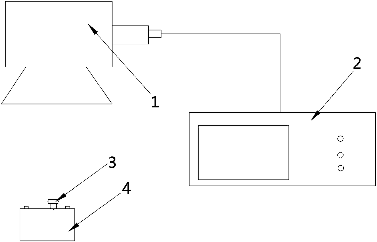
[0030] The invention provides a welding system for battery sealing nails, see figure 1 , the system includes a vibrating mirror 1, a fiber laser 2 and an air blowing device 3, wherein the vibrating mirror 1 is arranged directly above the blowing device 3, and is connected to the fiber laser 2 through an optical fiber, The fiber laser 2 is used to emit laser light of a certain power, the vibrating mirror 1 is used to receive the laser light emitted by the fiber laser 2, and output the laser light according to the preset welding trajectory for laser welding, and the blowing device 3 is used to provide a relatively sealed Welding environment.

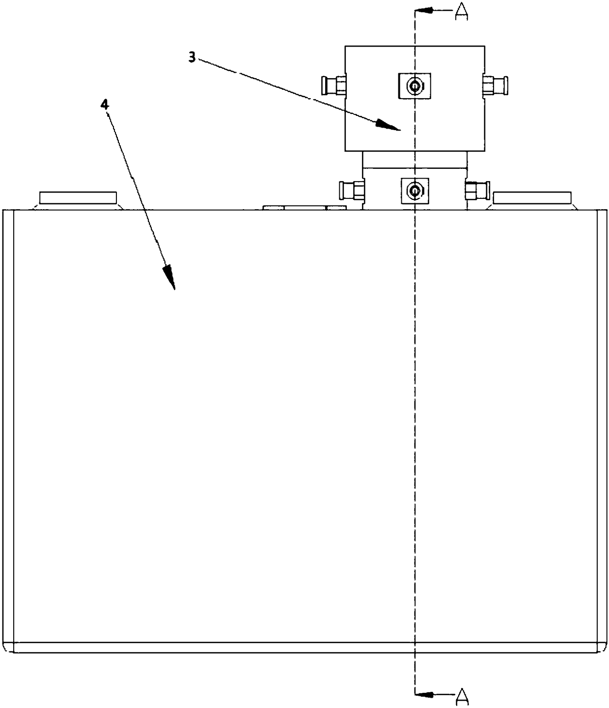
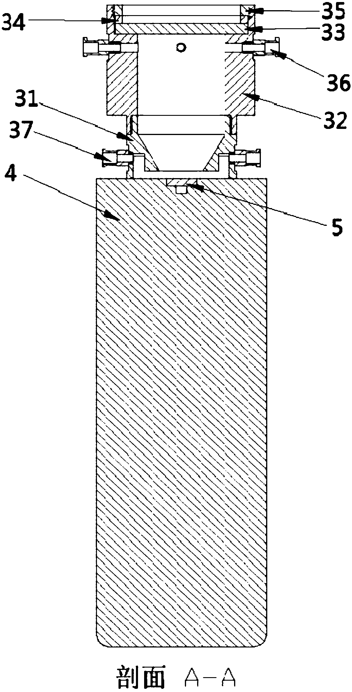
[0031] refer to figure 2 , the figure is a front view of the connection structure between the air blowing device 3 and the battery 4. In the embodiment of the present invention, the lower part of the air blowing device 3 is closely attached to the battery 4, so that a sealed air blowing environment can be formed , prevent external air f...

Embodiment 2

[0041] The present invention also provides a welding method applied to the battery sealing nail welding system described in Embodiment 1, see Figure 4 , the welding method comprises the steps of:

[0042] S1: setting the vibrating mirror directly above the battery, making the vibrating mirror coaxial with the sealing nail on the battery, and adjusting the height between the vibrating mirror and the surface of the weld;

[0043] In the embodiment of the present invention, the sealing nail 5 of the battery 4 is welded by combining the vibrating mirror 1 with the fiber laser 2. The emitted laser coincides with the weld seam to be welded, thus making the welding more accurate;

[0044] In the embodiment of the present invention, by designing the welding track of the galvanometer 1 during welding on the galvanometer control software, the welding operation of the galvanometer 1 includes three sections of welding tracks connected in sequence. In this embodiment, the first section ...


PUM


Abstract

The invention discloses a welding system and method for battery sealing nails, and relates to the field of battery laser welding. The welding system comprises a galvanometer, a fiber laser and an airblowing device, wherein the galvanometer is arranged right above the air blowing device and is connected with the fiber laser through an optical fiber. The method comprises the steps that the galvanometer is arranged right above a battery, so that the galvanometer and the sealing nails on the battery are coaxial, and the height between the galvanometer and the surface of a welding seam is adjusted; the air blowing device is tightly attached to the battery, so that the air blowing device is enabled to be coaxial with the sealing nails; and the air blowing device is started, the fiber laser is started, the input speed and the extraction speed of protection air of the air blowing device are controlled, and the galvanometer is enabled to carry out laser welding on the sealing nails according to a preset welding track. According to the welding system and method for the battery sealing nails, the welding system is simple in overall structure, based on the method, the welding speed is high, the protection air flow and the pressure in the welding process are uniform, the stability is good, the surface of the welding seam is flat and smooth after the welding is completed, and the fusion depth and fusion width are high in consistency.

Description

technical field [0001] The invention belongs to the field of battery laser welding, and in particular relates to a welding system and method of a battery sealing nail. Background technique [0002] With the rapid development of new energy vehicles, the power battery manufacturing industry has attracted more and more attention. Power battery sealing nail welding is one of the key processes in power battery manufacturing: after the battery cell is packaged into the battery case, a liquid injection hole is usually left on the case for electrolyte injection; after the electrolyte is injected, Sealing nails need to be welded to seal the shell; the existing technology of welding sealing nails, on the one hand, has slow welding speed, large welding equipment, and poor stability; on the other hand, the weld surface is uneven and clean, and deep penetration Wide consistency is poor. Contents of the invention [0003] In order to solve the above-mentioned problems of slow welding ...

Claims


Application Information

Patent Timeline
IPC IPC(8): B23K26/12B23K26/24B23K26/70
CPCB23K26/12B23K26/24B23K26/70
Inventor 刘继国刘昊胡勇雷鹏飞徐作斌高云峰
Owner HANS LASER TECH IND GRP CO LTD
Why Eureka
Try Eureka