Three-phase automatic balancing device with reactive compensation

An automatic balancing and three-phase technology, applied in reactive power compensation, reactive power adjustment/elimination/compensation, circuit devices, etc., can solve problems such as overvoltage instantaneous voltage, reduced output of distribution transformers, and shortened service life. Fast response and reduced transformer loss

Inactive Publication Date: 2019-03-22
湖南长高思瑞自动化有限公司
View PDF6 Cites 1 Cited by
  • Summary
  • Abstract
  • Description
  • Claims
  • Application Information

AI Technical Summary

Problems solved by technology

[0005] 1) The active power or power loss of the line increases
[0006] 2) Increased power loss of distribution transformers
[0007] 3) The output of the distribution transformer is reduced
[0008] 4) The operating temperature of the distribution transformer rises and the service life is shortened
[0009] 5) The neutral point is displaced, and the three-phase voltage of the distribution transformer is unbalanced
[0013] Although these two methods can achieve the purpose of three-phase balance, but the former is adjusted by manual commutation, which requires power failure in the low-voltage station area
Although the installation of an automatic phase change switch does not require a power outage and can auto

Method used


Image

  • Three-phase automatic balancing device with reactive compensation
  • Three-phase automatic balancing device with reactive compensation
  • Three-phase automatic balancing device with reactive compensation

Examples


Embodiment Construction

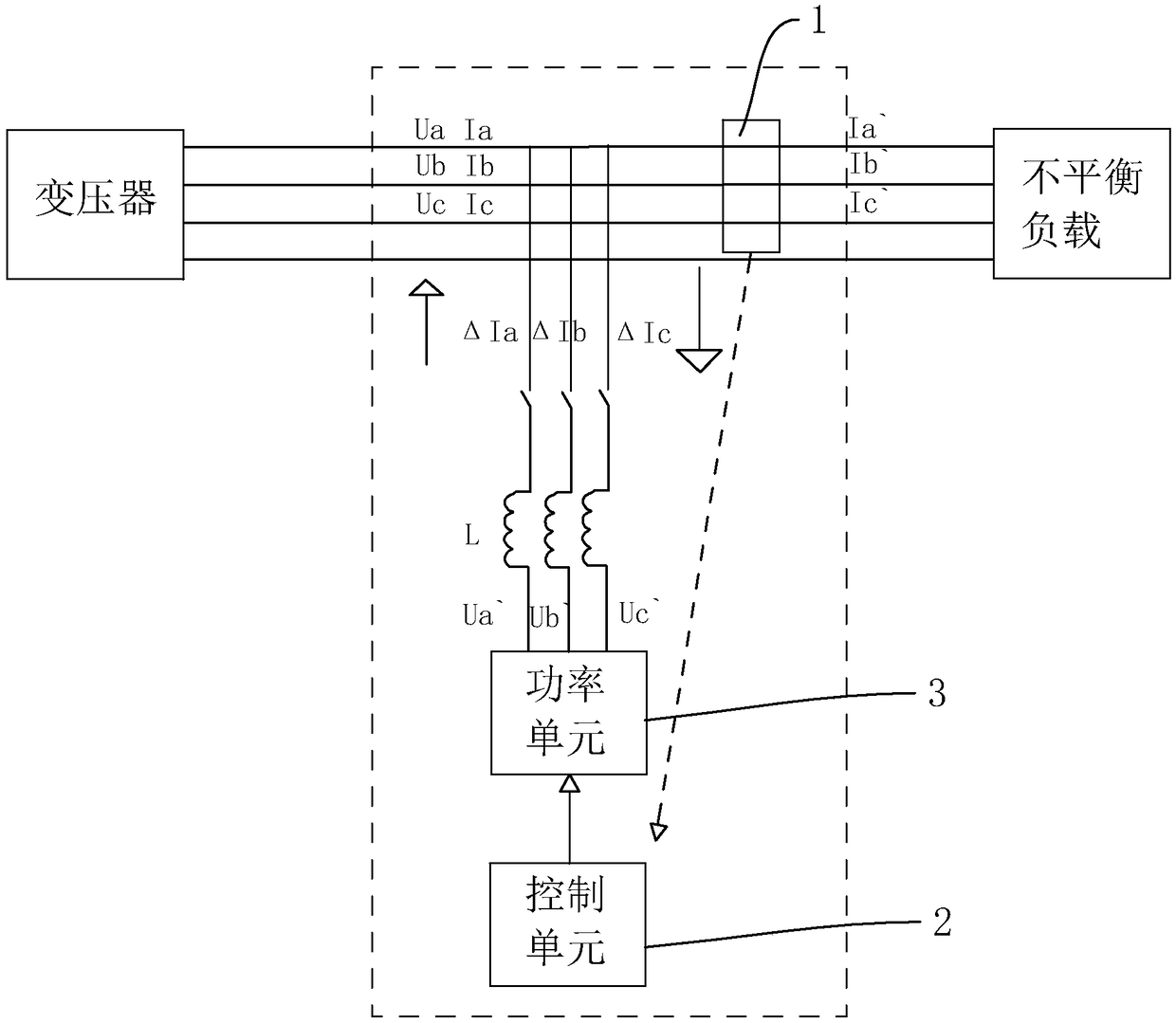
[0034] Such as Figure 1-Figure 4 Shown is a three-phase automatic balancing device with reactive power compensation of the present invention, connected to the power grid between the load and the transformer, including: an acquisition unit 1 for collecting voltage and current data of the load, a control unit 2, and a power unit 3. The acquisition unit 1 is connected to the signal input terminal of the control unit 2, the control unit 2 is connected to the control terminal of the power unit 3, and the power unit 3 is electrically connected to the incoming line terminal of the load through a reactor.

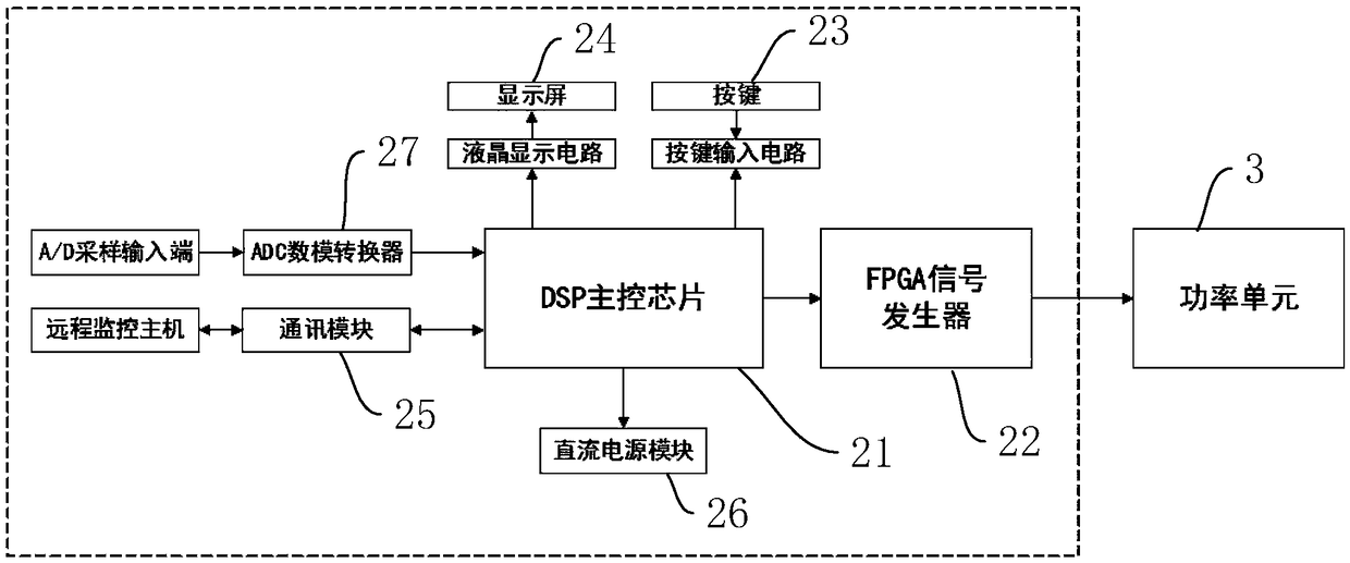
[0035] Wherein, the acquisition unit 1 includes a current transformer, a voltage transformer, an inverse operational amplifier circuit and a passive filter circuit; the control unit 2 includes a DSP main control chip 21, an FPGA signal generator 22, and also includes an ADC digital-to-analog converter, a current The transformer and the voltage transformer are respectively connecte...


PUM


Abstract

The invention discloses a three-phase automatic balancing device with reactive compensation, which is arranged between a load and a transformer and comprises an acquisition unit, a control unit and apower unit. The acquisition unit is connected with the signal input end of the control unit; the control unit is connected with the control end of the power unit, and the power unit is electrically connected with the wire inlet end of the load through an electric reactor; the acquisition unit comprises a current transformer and a voltage transformer; the control unit comprises a DSP main control chip and an FPGA signal generator, and the power unit comprises an H-bridge type multi-level circuit composed of a plurality of insulated gate bipolar transistors; the current transformer and the voltage transformer are connected with the signal input end of the DSP main control chip; the DSP main control chip is connected with the control end of the H-bridge type multi-level circuit through the FPGA signal generator, and the H-bridge type multi-level circuit is connected with the wire inlet end of the load through the reactor so as to output three-phase imbalance compensation currents. The device can automatically solve the problem of unbalanced three-phase loads, manual intervention is not needed, and worry and labor are saved.

Description

technical field [0001] The invention relates to the field of power distribution and utilization, in particular to a three-phase automatic balancing device with reactive power compensation. Background technique [0002] In recent years, my country's distribution network construction investment has continued to increase, and the development of distribution network has achieved remarkable results. However, there is still a gap between the level of electricity consumption and the international advanced level. The development of urban and rural areas is unbalanced, and the quality of power supply needs to be improved. [0003] In the low-voltage three-phase four-wire system of urban residents and rural power supply systems: because most of the power consumers are single-phase loads or mixed single-phase and three-phase loads, and the loads are different and the power consumption time is different. Therefore, the unbalanced current among the three phases in the grid exists objecti...

Claims


Application Information

Patent Timeline
IPC IPC(8): H02J3/26H02J3/18
CPCH02J3/1842H02J3/185H02J3/26Y02E40/30Y02E40/50
Inventor 雷波
Owner 湖南长高思瑞自动化有限公司
Why Eureka
Try Eureka