
Magnetostrictive/resonator series connection composite resonant magnetic sensor

A magnetostrictive and magnetic sensor technology, applied in the field of magnetic sensors, can solve the problem of limited frequency variation, such as the magnetostrictive coefficient, and achieve the effects of eliminating signal processing circuits, strong anti-noise interference ability, and reducing costs.

Inactive Publication Date: 2019-03-26
NANJING UNIV OF SCI & TECH
View PDF5 Cites 7 Cited by
  • Summary
  • Abstract
  • Description
  • Claims
  • Application Information

AI Technical Summary

Problems solved by technology

However, the structure of the sensor combines the stretchable plate and the tuning fork resonator in a "parallel" manner. In this structure, the deformation of the tuning fork resonator is less than or equal to the magnetostrictive elongation, and the frequency change is limited by the magnetostriction. Expansion coefficient

Method used


Image

  • Magnetostrictive/resonator series connection composite resonant magnetic sensor
  • Magnetostrictive/resonator series connection composite resonant magnetic sensor
  • Magnetostrictive/resonator series connection composite resonant magnetic sensor

Examples


Embodiment 1

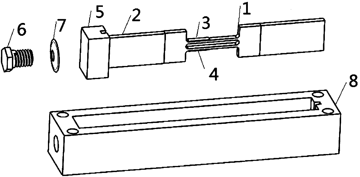
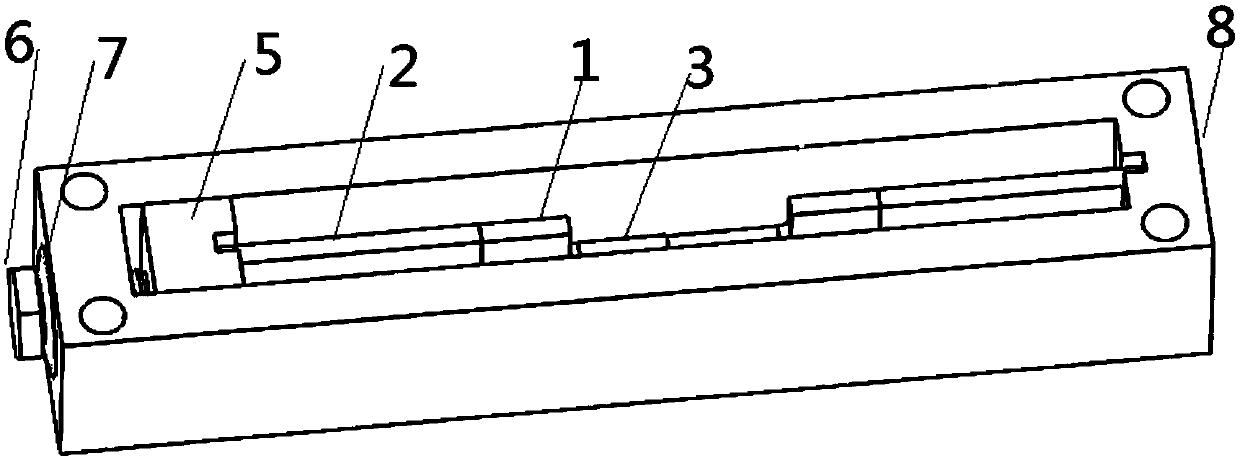
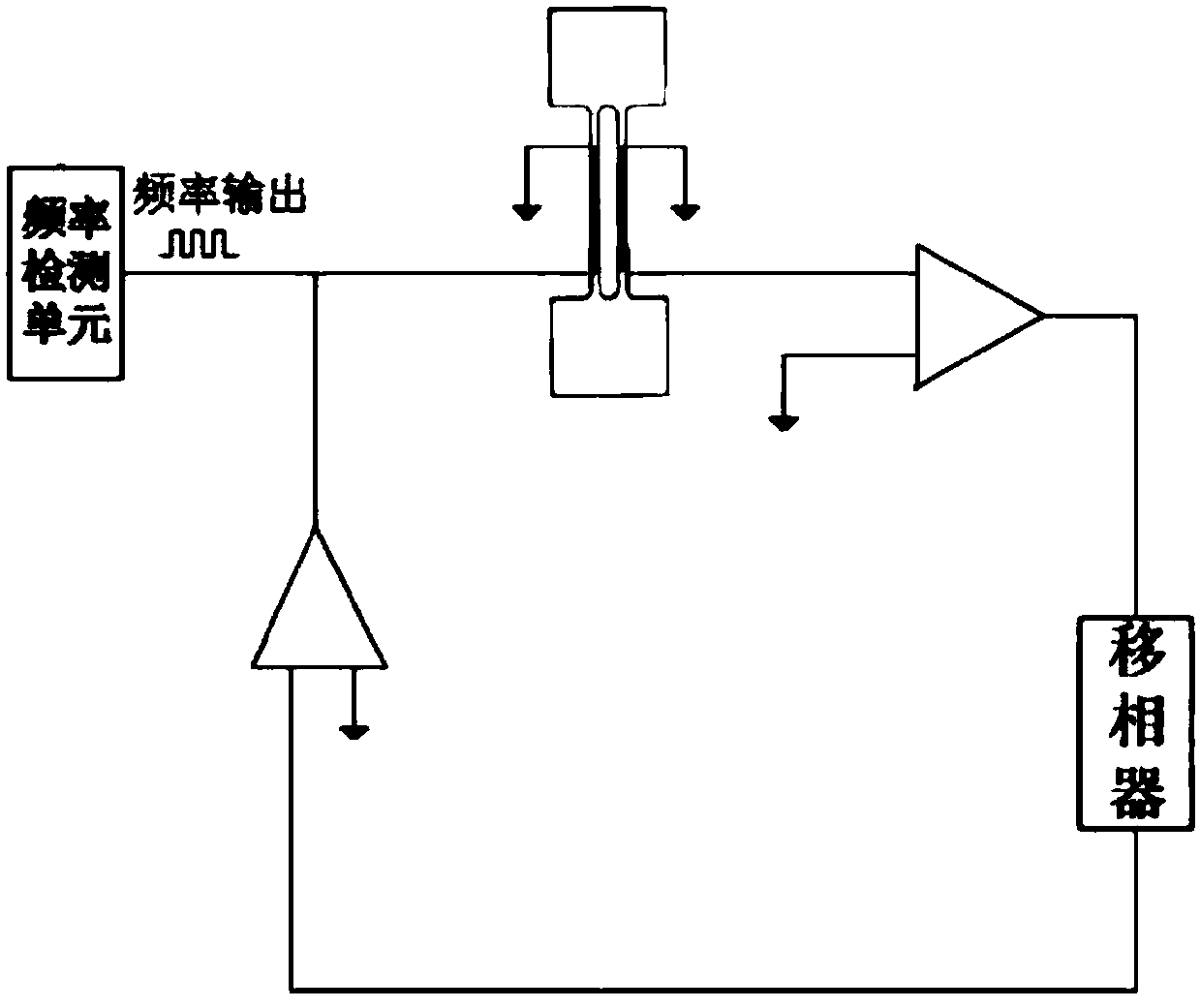
[0032] combine figure 1 and figure 2 , in this embodiment, a resonant magnetic sensor with a digital frequency output magnetostrictive / resonator series composite, including two magnetostrictive plates 2, a metal tuning fork resonator 1, a fixed support structure, an oscillating circuit, and a frequency detection unit, wherein the two ends of the metal tuning fork resonator 1 are respectively connected to one end of the corresponding magnetostrictive sheet 2; The other end of the stretchable sheet is snapped into the groove of the spacer 5; there is a threaded hole on one side of the packaging shell 8, and the spacer 5 is fastened to the threaded hole by the fastening screw 6 and the disc spring 7, thereby resonating the metal tuning fork The device 1 and the magnetostrictive sheet 2 are fixed in the groove of the fixed support structure through the pad 5; the root of the vibrating beam of the metal tuning fork resonator 1 is bonded with a piezoelectric drive unit 3 and a pie...

Embodiment 2

[0037] combine Figure 4 and Figure 5 As shown, the tuning fork resonator in this embodiment is a quartz tuning fork resonator 10, the fixed support structure is a base 11, grooves are provided at both ends of the base 11, and the other ends of the magnetostrictive sheet 2 are respectively fixed in the grooves , and respectively fix a pressing piece 9 on the port where the two magnetostrictive pieces 2 are located in the groove. Adhesive, welding and other methods are used to closely combine the pressing piece 9 with the grooves at both ends of the base 11, so that the end of the magnetostrictive sheet inserted into the groove is fixed.

[0038] The quartz tuning fork resonator 11 is a double-beam quartz tuning fork fixed at both ends, and there are electrode pads at both ends of the tuning fork for connecting to an external oscillating circuit. The quartz tuning fork resonator 11 works in the bending vibration mode, and the vibration directions of the two beams are symmetr...


PUM


Abstract

The invention discloses a magnetostrictive / resonator series connection composite resonant magnetic sensor and belongs to the magnetic sensor field. The sensor comprises two magnetostrictive plates, atuning fork resonator, a fixed support structure, an oscillating circuit and a frequency detecting unit. The two ends of the tuning fork resonator are connected to one ends of the corresponding magnetostrictive plates. The tuning fork resonator and the magnetostrictive plates are fixed in the fixed support structure. The tuning fork resonator and the oscillating circuit are connected to form an oscillating circuit loop. The oscillating circuit carries out self-oscillation and outputs an oscillating signal according to the resonant frequency of the tuning fork resonator, and the tuning fork resonator generates resonance according to the oscillating signal. The frequency detecting unit is used for detecting the resonant frequency of the tuning fork resonator. By using the magnetostrictive / resonator series connection composite resonant magnetic sensor, through increasing the length of the magnetostrictive plates, large telescopic deformation is generated so as to improve sensitivity.

Description

technical field [0001] The invention belongs to the field of magnetic sensors, in particular to a resonant magnetic sensor with magnetostriction / resonator series compound. Background technique [0002] Common types of high-precision magnetic sensors mainly include superconducting quantum interference magnetometer (SQUID), electromagnetic induction magnetic sensor, fluxgate magnetic sensor, nuclear magnetic resonance magnetic sensor, optical pump magnetic sensor, giant magneto-impedance sensor, etc. However, there are always some unsatisfactory places in the existing magnetic sensors. In order to develop new magnetic sensors with high precision and high cost performance, people have never stopped researching on new principles and methods of magnetic sensors. The resonant magnetic sensor with digital frequency output has received widespread attention due to its strong anti-interference ability, low power consumption, and simple sensor circuit. Invention patent (a high-Q reson...

Claims


Application Information

Patent Timeline
Patent Type & Authority Applications(China)
IPC IPC(8): G01R33/06G01R33/10
CPCG01R33/06G01R33/10
Inventor 卞雷祥吴一凡
Owner NANJING UNIV OF SCI & TECH
Learn More