
Device, system and process for formaldehyde concentrating

A formaldehyde and cylinder technology, which is applied in the field of high-efficiency and stable operation of formaldehyde concentration processes and devices, can solve the problems of low concentration and separation efficiency, easy generation of paraformaldehyde, large steam consumption, etc., and achieves simple inspection and extended stable operation of equipment. Period, the effect of increasing the heat transfer area

Active Publication Date: 2019-03-29
YANKUANG GRP CO LTD
View PDF7 Cites 2 Cited by
  • Summary
  • Abstract
  • Description
  • Claims
  • Application Information

AI Technical Summary

Problems solved by technology

[0004] But, with regard to the formaldehyde solution vacuum flash concentration device known to the inventor, it has the following two disadvantages: the one, the concentration and separation efficiency is low, the vapor-liquid ratio is 1.25:1~1.5:1, the amount of concentrated formaldehyde is few, and the dilute produced When the aldehyde solution is recovered, the steam consumption is large (steam consumption: dilute aldehyde amount = 0.8-1:1); second, when the dilute formaldehyde solution is condensed by flash evaporation, paraformaldehyde is easily produced, which will cause equipment blockage after accumulation in the condenser
After the equipment is clogged, the conventional treatment method is to clean it with hot water or stop it. It takes a long time to wash it with hot water or stop it, usually 10h to 24h, and the cost of recycling the cleaning solution is high.
[0005] Therefore, aiming at the problems of low separation efficiency and short operation period of the formaldehyde concentration technology known to the inventors, the present disclosure is thus proposed

Method used


Image

  • Device, system and process for formaldehyde concentrating
  • Device, system and process for formaldehyde concentrating
  • Device, system and process for formaldehyde concentrating

Examples


Embodiment Construction

[0023] It should be noted that the following detailed description is exemplary and intended to provide further explanation of the present disclosure. Unless defined otherwise, all technical and scientific terms used herein have the same meaning as commonly understood by one of ordinary skill in the art to which this disclosure belongs.

[0024] It should be noted that the terminology used herein is only for describing specific embodiments, and is not intended to limit the exemplary embodiments according to the present disclosure. As used herein, unless the context clearly dictates otherwise, the singular is intended to include the plural, and it should also be understood that when the terms "comprising" and / or "comprising" are used in this specification, they mean There are features, steps, operations, means, components and / or combinations thereof.

[0025] A typical implementation of the present disclosure provides a formaldehyde concentration vacuum separator, which is a ci...


PUM


Abstract

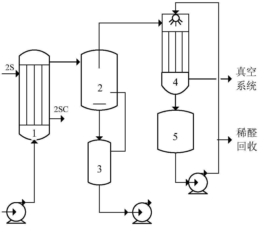
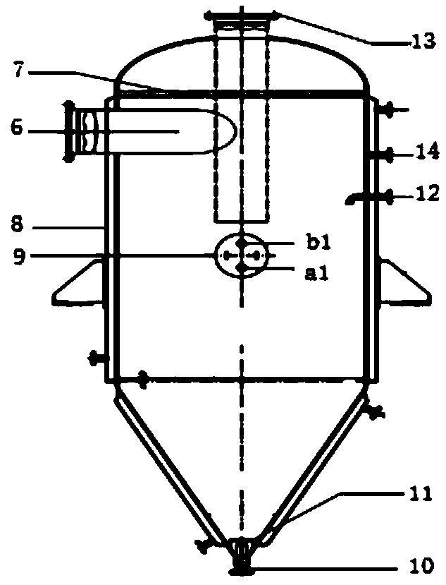
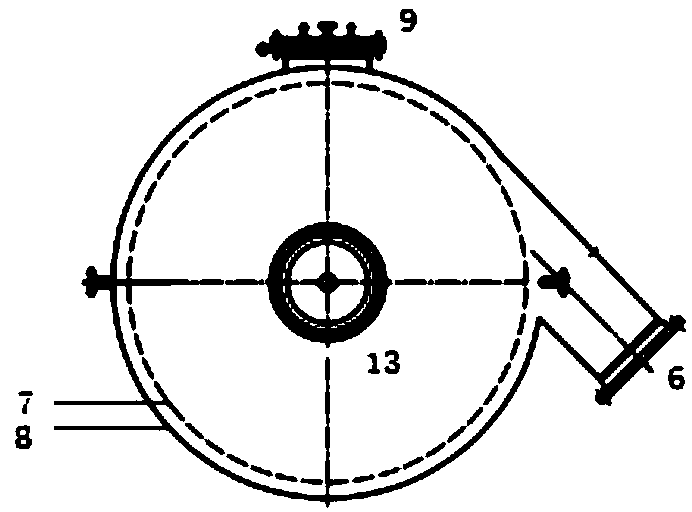
The invention discloses a device, a system and a process for formaldehyde concentrating. The device is a formaldehyde concentrating vacuum separator, which is a circular cylinder structure and which is provided with a jacket on the external wall. One end of the circular cylinder structure is provided with a gas phase outlet, and the other end is provided with a liquid phase outlet. The cylinder wall of the circular cylinder structure is provided with a material inlet pipe. The material discharging direction of the material inlet pipe is tangent to the wall of the circular cylinder structure. The material inlet pipe is adjacent to the gas phase outlet, and the cylinder wall of the circular cylinder structure is provided with an annular liquid retaining ring the center of which is on the axis of the circular cylinder structure. The liquid retaining ring is located between the material inlet pipe and the gas phase outlet. The gas phase outlet is provided with a gas discharging pipe. The gas inlet of the gas discharging pipe is between the material inlet pipe and the liquid phase outlet. The device enables greatly improved concentration separation efficiency and reduces the recovery amount of lean formaldehyde and steam consumption.

Description

technical field [0001] The invention relates to the technical field of formaldehyde concentration in a polyoxymethylene production process, and mainly relates to a process and a device for formaldehyde concentration with high efficiency and stable operation. Background technique [0002] The statements herein merely provide background information related to the present invention and may not necessarily constitute prior art. [0003] In the production process of polyformaldehyde copolymer, the synthesis of monomeric paraformaldehyde is mainly based on the concentrated formaldehyde solution with a concentration of 65% to 75% as the raw material. host. In a polyoxymethylene copolymer production process known to the inventor: formaldehyde solution with a concentration of about 40% is used to pressurize and gasify, then vacuum flash evaporates and concentrates to produce concentrated formaldehyde, and after the flash steam at the top of the vacuum flash evaporator is cooled, a 1...

Claims


Application Information

Patent Timeline
Patent Type & Authority Applications(China)
IPC IPC(8): B01D3/06B01D3/10B01D1/30B01D1/22B01D1/00
CPCB01D1/00B01D1/22B01D1/30B01D1/305B01D3/06B01D3/10
Inventor 李志远龙厚坤张华徐开锋王广义王霜霜孟凡超孔令腾姜存华康亚立
Owner YANKUANG GRP CO LTD
Learn More