A landing ladder with dual functions of unfolding and retracting
A dual-function, landing ladder technology, applied in the aerospace field, can solve problems such as complex structure and high quality of landing ladders, and achieve the effect of solving high quality and reducing consumption
- Summary
- Abstract
- Description
- Claims
- Application Information
AI Technical Summary
Problems solved by technology
Method used
Image
Examples
Embodiment 1
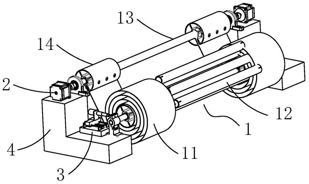
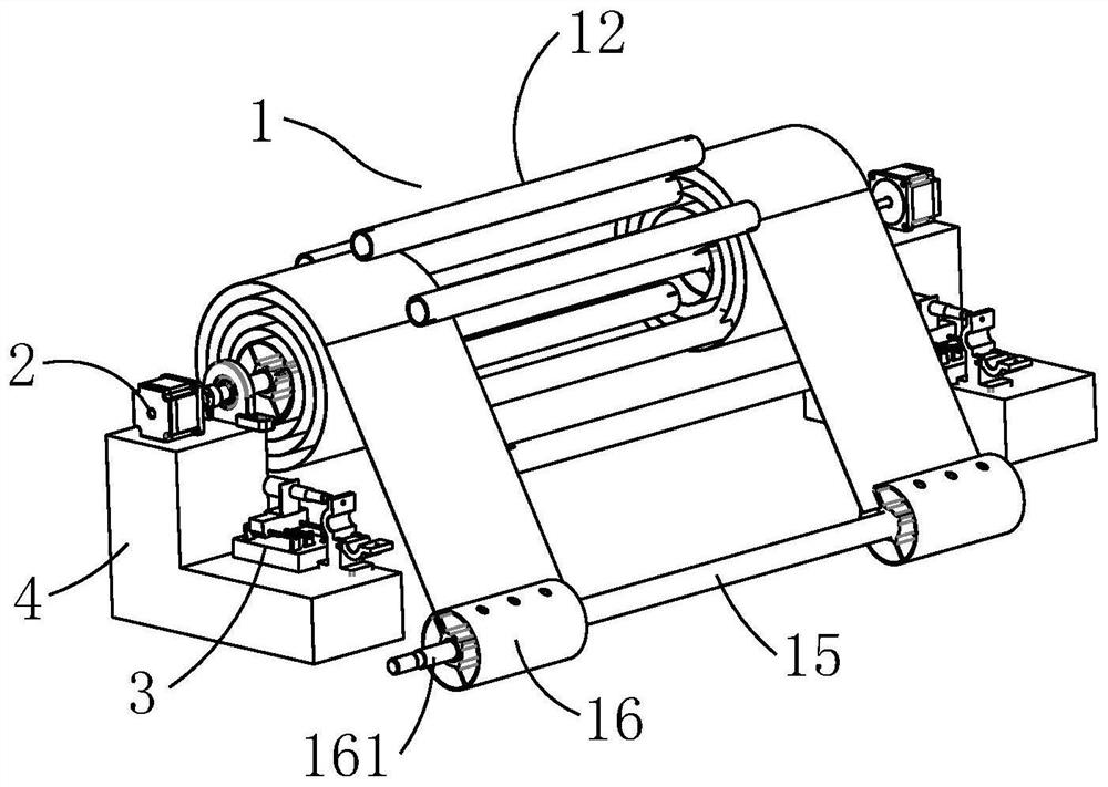
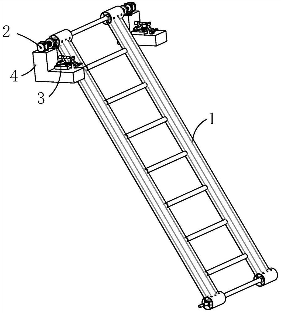
[0037] Such as Figure 1-3 As shown, a landing ladder with dual functions of unfolding and retracting includes a main ladder structure 1, a locking mechanism 3 and a rotating retracting mechanism 2; the main ladder structure 1 has a shape memory effect, and the main ladder structure 1 includes a first end and a second end. The two ends; the rotary retracting mechanism 2 is connected to the first end, and the rotary retracting mechanism drives the first end to rotate; the locking structure is detachably connected to the second end, and the locking mechanism 3 is used to lock or release the second end;
[0038] In this embodiment, the main ladder structure 1 can be unfolded or curled; in the state where the locking mechanism 3 locks the second end, the main ladder structure 1 is curled on the first end or the second end; when the locking mechanism 3 releases the second end Next, the main ladder structure 1 is unfolded. As a result, the main ladder structure 1 cooperates with th...
Embodiment 2
[0041] Such as figure 1 , 2 , 3, compared with the above embodiment, the main ladder structure 1 in this embodiment includes a beam 12, a first connecting rod 13, a second connecting rod 15 and a pod rod 11 made of shape memory polymer composite material.
[0042] There are two pod bars 11, one end of each pod bar 11 is connected to a connector 14, and the other end is connected to a loader 16; the two ends of the first connecting bar 13 respectively pass through a connector 14, and the connector 14 and the second A connecting rod 13 constitutes the first end, and the connector 14 is connected to the rotary retracting mechanism 2; the two ends of the second connecting rod 15 respectively pass through a loader 16, and the end of the loader 16 away from the second connecting rod 15 is provided with an auxiliary rod 161 , the loader 16 and the second connecting rod 15 form the second end, the loader 16 is connected to the locking mechanism 3 through the auxiliary rod 161; the be...
Embodiment 3
[0049] Such as Image 6 As shown, compared with the above-mentioned embodiments, the locking mechanism 3 in this embodiment includes a base 31 , a screw slide mechanism 32 , a third driving motor 33 , a support base 34 , a transmission shaft 35 and a rotating support 36 .
[0050] The screw slide mechanism 32 is arranged on the base 31; the support seat 34 is arranged on the slide table 322 of the screw slide mechanism 32; the third drive motor 33 is arranged on the support seat 34; the transmission shaft 35 is connected to the third drive motor 33, the transmission shaft 35 is provided with a screw 351; the rotating support 36 is provided with a support body 361 and a rotating block 362, and the supporting body 361 is provided with a draw-in groove 363 for engaging the second end; one end of the rotating block 362 is of a rotary type Connecting the support body 361 , the rotating block 362 opens and closes the locking slot 363 through the screw 351 , thereby locking and relea...
PUM
 Abstract
Description
Claims
Application Information
 - R&D
- Intellectual Property
- Life Sciences
- Materials
- Tech Scout
- Unparalleled Data Quality
- Higher Quality Content
- 60% Fewer Hallucinations
Browse by: Latest US Patents, China's latest patents, Technical Efficacy Thesaurus, Application Domain, Technology Topic, Popular Technical Reports.
© 2025 PatSnap. All rights reserved.Legal|Privacy policy|Modern Slavery Act Transparency Statement|Sitemap|About US| Contact US: help@patsnap.com


